

Drawings and documents
National Archives restored drawings: drawing
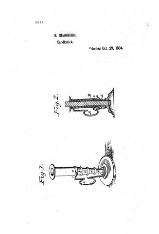
B. Dearborn's Patent Drawing for a Economical Candlestick

National Archives, Restored Patent Drawings (Record Group 241) · Full-size scan at the National Archives · Catalog record
Show the text on the drawing Hide (111 words)
Words on the drawing as machine-read by the National Archives; not checked. Useful mainly for searching.
67. LAMPS & GAS FITTINGS. / $1~ / [90] Candlesticks. / B. DEARBORN'S / CLASSIFICATION / 581+ / Economical Candlestick. / Patented Oct 29th 1804. / DIVISION. / the / References nces / a.b.c.d. Tubes._A. Spring. / B. Solid cylinder. / 010 / This is to certify that this drawing was made under the direction of the Commissioner of / Patints in conf sriming to the provision of the act of the 300g seat. jub from and in / accordance with the specify is ation on which letters patent were g ranted to said B.Dearborn / dated Oct. and recorded anew on he 5th day of Apri ? 1838. / Hemy 1 Ellmonth / Bormissioner of Patents
USPTO scan
The patent as scanned by the USPTO
-
 Page 1
-
 Page 2


U.S. Patent and Trademark Office · Google Patents
Show the transcription Hide (386 words)
Machine transcription (LightOnOCR) of the pages as scanned by the USPTO, most of them the handwritten copies made when the records were restored after the 1836 fire. Not checked; it can misread handwriting, so compare it with the scan.
Page 1.
581X
B. DEARBORN.
Candlestick.
Patented Oct. 29, 1804.
Fig. 1.
Fig. 2.
Page 2.
Benjamin Dearborn of Massachusetts.
Letters Patent
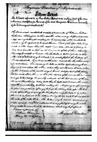
The Schedule referred to in these Letters Patent and making part of the same containing a description in the words of the said Benjamin Dearborn himself of the "Economical candlestick."
The Economical candlestick consists of a number of tubes or hollow cylinders sliding one within another of as many different grades in size as may be thought necessary for the various sizes of the candlesticks which may be required to be used therein. Each of the upper tubes being made a little longer than the next lower one, admits of fixing a ring or a handle or both on the lower ends of all of them, whereby they may be raised or lowered. In the center a solid cylinder or tube (the ends of which may be closed) is made fast to the bottom of the candlestick by a screw mechanism, round this the others move up and down. The innermost tube or solid cylinder may be so long as to rise above the others when they are drawn down, when by the last point of the candle may be burnt independent of the sliding tubes and above them, so that the shadow of the rim on the oil must in large tubes may be greatly reduced at the last remains of the same. The said sliding tubes will thus be kept cool to receive the next candle immediately without melting it. A spring or springs may be fixed in a variety of ways to keep the sliding tubes up. The best mode of making a spring for this purpose may perhaps be by a handle which is fastened to the bottom having its top made to spring against the side of the outer tube. The bottom may be round, square or any shape required, and this instrument or any part of it may be made of any metal or noncombustible substance which may be preferred.
Signed in presence of
William Sherman
Henry H. Fitzhugh
Benjamin Dearborn
336 words (Granted October 29, 1844)
About this record
- Patentee
- Jim Shaw's X-patent list
- Date
- the Name and Date index of patents, USPTO records, Jim Shaw's X-patent list
- Invention
- the Name and Date index of patents
- Listed in
- the Name and Date index of patents, USPTO records, Jim Shaw's X-patent list, S. A. Elliot's printed list of patents, Burke's List of Patents (1847)
- S. A. Elliot's printed list of patents gives the same name and date.
- Burke's 1847 Patent Office list gives the same patent.