

Drawings and documents
National Archives restored drawings: drawing
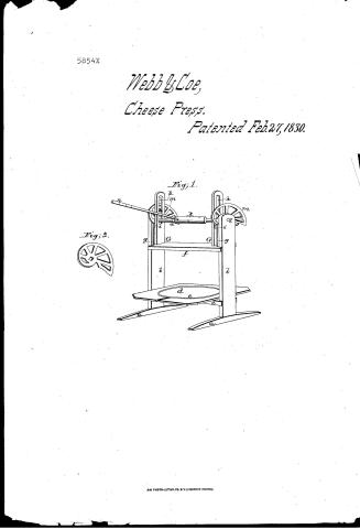
R. Webb and J. Coe's Patent Drawing for a Cheese Press

National Archives, Restored Patent Drawings (Record Group 241) · Full-size scan at the National Archives · Catalog record
Show the text on the drawing Hide (68 words)
Words on the drawing as machine-read by the National Archives; not checked. Useful mainly for searching.
100. PRESSES. / [45] Cheese / Chesses Cheese Pre / 11-11 / Presses / Packing cheese / CLA ESIFICATION / 5854-7 / R. Webb I Coc's / DIV TSION / vol.19.61 / Presses- - / Patented 27th / Figl / weighted / oz / Fig2. / be / Patent Office 24 Oct 1839 / Made under the direction of the Commipioner of / Patents, in conformity with act. 3d March 1837. / Menuf.Sumorth / Comm. of Satents.
USPTO scan
The patent as scanned by the USPTO
-
 Page 1
-
 Page 2
-
 Page 3
-
 Page 4
-
 Page 5
-
 Page 6


U.S. Patent and Trademark Office · Google Patents
Show the transcription Hide (1,705 words)
Machine transcription (LightOnOCR) of the pages as scanned by the USPTO, most of them the handwritten copies made when the records were restored after the 1836 fire. Not checked; it can misread handwriting, so compare it with the scan.
Page 1.
5854X
Webb & Coe,
Cheese Press.
Patented Feb. 27, 1830.
Fig. 1.
Fig. 2.
AM. PHOTO-LITHO. CO. N.Y. (OSBORNE'S PROCESS)
Page 2.
Feb 27, 1830
Reynolds Webb & Jonathan Coe
Letters Patent
X5854
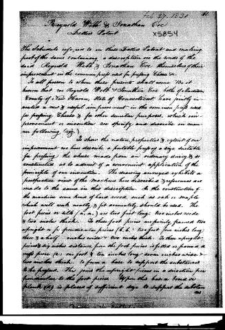
The Schedule referred to in these Letters Patent and making part of the same containing a description in the words of the said Reynolds Webb & Jonathan Coe themselves of their improvement in the common press used for pressing Cheese &c.
To all person to whom these presents shall come. Be it known that we Reynolds Webb & Jonathan Coe both of Madison, County of New Haven, State of Connecticut, have jointly invented a new & useful improvement in the common press used for pressing Cheese & for other similar purposes, which improvement or invention we specify and describe in manner following (viz.)
To show the nature, properties & extent of our improvement we have described a portable press of a size suitable for pressing the cheese made from an ordinary dairy & constructed as to admit of a convenient application of the principle of our invention. The drawing annexed exhibits a perspective view of the machine here described & references are made to the same in this description. In the construction of the machine some kind of hard wood, such as oak or maple which will wash neatly & fit accurately should be used. The foot pieces or sills (a, a,) are two feet long, two inches wide & two inches thick. To these foot pieces are firmly framed two upright or perpendicular pieces (b, b,) two feet four inches long three & a half inches wide & two inches thick. To these upright pieces & fifty inches distance from the foot pieces is fitted or framed a cross piece (c,) one foot & ten inches long, seven inches wide & two inches thick, to form a base to support the substances to be pressed. This joins the upright pieces in a direction perpendicular to the foot pieces. Upon this base a board or plank (d) is placed of sufficient size to support the substan
Page 3.
X5854
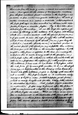
to be furnished with a channel (e) cut in a circular cross from & leading off from one edge of the frame in order to relieve any liquid matter which may be discharged— A second cross piece (f) parallel to the first, one foot & ten inches long, makes wide & two inches thick, is fitted with a notch at each end of the width of the perpendicular pieces so as to slide freely up & down as the pressure is applied or removed— Into each end of this last piece are framed two upright or perpendicular pieces (g.g.) (y.y.) & the two pieces which form each pair are three fourths of an inch distant from each other. The two outer pieces of each pair (g.g.) are four & a half inches long & three & a half inches wide & three fourths of an inch thick & rounded at top. The two inner pieces (y.y.) are one foot three inches long, three & a half inches wide & one inch thick, & in the upper part of these inner pieces are two mortises or openings (h.h.) eight and a half inches long & two inches wide rounded at each end of the openings & the whole pieces rounded at the top. Between each of these pairs of upright pieces & one & a half inch distance from the ends of the shorter pieces is placed a small wheel (i.i.) two inches in diameter & three fourths of an inch thick with pins running thru the pairs of upright pieces & thru the centre of each wheel half an inch in diameter & the the wheels & pins are formed of iron, brass, or other hard metal. There is a third cross piece (k.) circular in its shape but largest in the middle. The circumference at the ends is six inches & in the middle eight inches with three or more holes near the middle one inch in diameter intended to receive a lever. This cross piece is one foot six inches long & in each end of it is placed a metal quidgon (l.) five inches in length which may run in a metal box placed in the upper part of each upright piece (h.h.) & three inches from the top of the same. The quidgons & boxes should be iron or brass or other hard metal. The two ends of the circular cross piece are made square for
Page 4.
the distance of one inch & a quarter from each end, & each side of the square is one inch & a half. Upon these square parts are fitted two curves or spirals, a scroll piece made of iron or other hard metal (m, m,) five eighths of an inch in thickness with open work & braces so as to secure both lightness & strength, but where these are not regarded they can be solid & there are to be so fitted as to run upon the wheels (i, i,) with accuracy. When the circular orifice piece (k,) is turned round by means of the lever (n,) of suitable length & size & fitted to enter the holes in the same, this lever also may have two or three or more notches or grooves cut round the same so that when a constant pressure is needed a weight may be hung up on the lever when in an elevated position & not slide down towards the circular orifice piece. The weight to be applied may be a stone, bag of sand, or other suitable heavy matter. When a constant pressure is not needed, any other common power may be applied. By varying the size & proportion of the parts pieces may be made larger or smaller according to the size to which they are to be applied, also the curves spiral or scroll pieces (m, m,) if shaped as represented in the annexed drawing, will by means of the projections (c, c,) fitting to the wheels (i, i,) when the orifice piece (f,) is raised as high as it can be, hold up & support the orifice piece (f,) from descending by its own weight, which may be some convenience in using the pump. The curves spiral or scroll pieces may be formed with the outer edge or periphery diverging more or less rapidly from the central point, but our experience leads us to the conclusion that a curve or spiral which at the point on the circumference, when it is first made to operate is one inch & a half distant, measured on a radius or minute from the centre of its motion in order to give it suitable thickness & strength, & at the distance of seven inches measured from the first mentioned point upon the periphery, has a
Page 5.
three inches from the centre of motion measured on a radius normal to it; and again at the distance of twenty inches, measured from the first mentioned point & measured on the perpendicular or outer curve, is five inches & one quarter distant from the centre of motion measured on a radius or ordinate, is but adapted to the props of the size we have described & in the same ratio or proportion for larger or smaller props. Fig 2 exhibits a spiral detached from the machine. To use the prop the crimp piece (f) is raised by blocking on the substance to be pressed, till the two wheels (i, i,) come in contact with the spiral pieces (m, m,) & if you wish to move the crimp piece (f) thru all the distance which it can be carried by the spirals (m, m,) you bring the wheels (i, i,) and the spirals (m, m,) in contact as near to the central points of the spirals (m, m,) as possible, then introduce the lever (n) into the holes in the circular crimp piece (h,) & the weight or other power is applied to the lever (n) causing the crimp piece (h) to revolve & carry with it the spirals (m, m,) which press upon the wheels (i, i,) which also revolve & the spirals (m, m,) press down the crimp piece (f,) with great force upon the substance placed under it & intended to be pressed, while the crimp piece (f,) by means of the mortises (k, k,) in the upright pieces (g, g,) is kept parallel to the base (c,) & base board (d,) & each side of the substance pressed is kept to the same thickness or width. This prop is simple in its construction easily managed & kept in order, portable & possesses great power, which is easily brought into operation & very little retarded or diminished by friction. With perhaps slight variations in construction props may be formed upon this plan, & with our improvements adapted to almost any purpose for which props are used. What we claim as our invention or improvement is the combination of the forms of the two and wedge or inclined plane by means of the circular crimp piece, the curved, spiral, or scroll pieces attached to the one
Page 6.
X5854
65.
being & operating on the two small wheels as described & set forth in the foregoing specification whereby great power to press is obtained & that power made to operate in a convenient cheap uniform manner & with but a small loss of power by friction. But we do not claim as any part of our invention the whole or any of the parts of the above described press now or formerly in use in the particular size or shape of the same any farther than is necessary to combine the above powers & bring them to operate in combination & remove or lessen friction during their operation.
Witnesses
Jonathan E. Wood
Suther Graue
Reynolds Webb
Jonathan Coe
1686 no 82
Toyd.
1856
Published accounts: journal notice
Notice in the monthly list of patents, with remarks
Journal of the Franklin Institute, new ser., vol. 5 (1830), p. 304 · View the page
39. For an improved Press for Pressing Cheese; Reynold Webb and Jonathan Coe, Madison, New Haven county, Connecticut, February 27.
Remarks. The follower of this press is acted upon by eccentrics placed at each end of a shaft, or windlass; the cheeks of the press rise in the ordinary manner, with a bed piece upon which to place the cheese, or other article to be pressed; the follower is notched to fit, and slide within the cheeks, as usual. An iron, or other friction roller, is placed on the upper side of the follower at each end. Above these a shaft, or windlass, is fixed, the gudgeons of which turn in the cheeks. Cast iron eccentrics, or curved pieces, which operate as progressive levers, are fixed upon the windlass, and act upon the friction rollers on the follower, the windlass being turned by a lever. Such a curvature may be given to these pieces as may best suit the purpose for which the press is to be used. The claim is to "the combination of the powers of the lever and wedge, or inclined plane, by means of the circular cross piece, [windlass] and the curved, spiral, or scroll pieces attached to the ends thereof, and operating on the small wheels, as described." "The patentees state that "this process is simple in its construction, easily managed, and kept in order, portable, and possesses great power, which is easily brought into operation, and very little retarded or diminished by friction."
About this record
- Patentee
- DATAMP
- Date
- the Name and Date index of patents, DATAMP, USPTO records
- Invention
- DATAMP
- Listed in
- the Name and Date index of patents, DATAMP, USPTO records, Jim Shaw's X-patent list, the Journal of the Franklin Institute, Burke's List of Patents (1847)
- Burke's 1847 Patent Office list gives the same patent.