

Drawings and documents
National Archives restored drawings: drawing
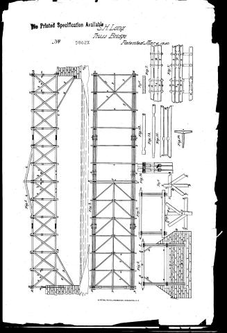
S. H. Long's Patent Drawing for Improvements in the Construction of Bridges

National Archives, Restored Patent Drawings (Record Group 241) · Full-size scan at the National Archives · Catalog record
Show the text on the drawing Hide (62 words)
Words on the drawing as machine-read by the National Archives; not checked. Useful mainly for searching.
14. BRIDGES. / Truss, / 3 S.HoLong's [21] Imp in the construction of Bridges / Fig-1 / Patented: 6th March 1830. / 5862-4 / be / Fig: / 2. / II / Patent Office 31st Aug 1841. / Francis Benne del / Made under the direction of the Commiprioner / of Patents, in conformity with act: 3d March 1837 / Menigh Sunomh / Comm of Patents
USPTO scan
The patent as scanned by the USPTO
-
 Page 1
-
 Page 2
-
 Page 3
-
 Page 4
-
 Page 5


U.S. Patent and Trademark Office · Google Patents
Show the transcription Hide (1,449 words)
Machine transcription (LightOnOCR) of the pages as scanned by the USPTO, most of them the handwritten copies made when the records were restored after the 1836 fire. Not checked; it can misread handwriting, so compare it with the scan.
Page 1.
No Printed Specification Available.
S. H. Long.
Truss Bridge.
No. 5862X.
Patented Mar. 6, 1830.
Page 2.
March 6, 1830
S. H. Spang
Letter of Patent
X5862
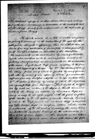
The Schedule refers to in these Letters Patent and making part of the same containing a description in the words of the said S. H. Spang himself of his improvement in the construction of wooden or frame Bridges.
The objects aimed at in this invention are greater simplicity & economy in the construction of Bridges together with greater strength & efficiency than has hitherto been obtained from any combination of principles or arrangement of parts heretofore adopted in the structure of this description.
The improvements under consideration by means of which the objects above mentioned are to be accomplished consist of the following Modifications or arrangements in the construction of the main longitudinal truss frames necessary to the formation and support of a bridge viz. 1st Two modes of applying the string pieces one of which is effected by means of wooden & the other by means of iron string pieces, of a construction different from any heretofore adopted in bridge architecture. 2nd A system of bracing by means of which the truss frames are exempted from leverage in that liable to be effected by such an action, & the steps or thrusts communicated by the braces are resisted by sheaves or steps as nearly as may be at right angles with the grain or fibres of the timber. 3rd A system of counter bracing by means of which the truss frames are rendered stiff & non-yielding & the bridge kept in uniform action whether loaded or unloaded. 4th A mode of furnishing the main braces and posts with metallic bearings by the introduction of thin plates of iron, copper or other suitable metal between the foot & toe of each main brace & the steps in the posts.
Page 3.
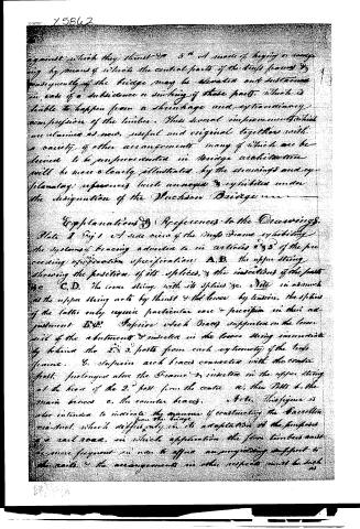
against which they thrust. 5th. A mode of keying or securing by means of which the central parts of the truss frames & consequently of the bridge may be elevated and sustained in case of a subsidence or sinking of those parts, which is liable to happen from a shrinkage and extraordinary compression of the timber. These several improvements which are claimed as new, useful and original together with a variety of other arrangements many of which are believed to be unprecedented in bridge architecture will be more clearly illustrated by the drawings and explanatory references here annexed & exhibited under the designation of the Jackson Bridge.
Explanations & References to the Drawings.
Plate 1 Fig 1. A side view of the truss frame exhibiting the system of bracing alluded to in articles 2 & 3 of the preceding specification. A.B. the upper string showing the position of its splices, & the insertions of the posts. C.D. the lower string with its splices &c. Note inasmuch as the upper string acts by thrust & the lower by tension, the splices of the latter only require particular care & precaution in their adjustment. E.F. Superior arch braces supported on the lower side of the abutments & inserted in the lower string immediately behind the 2nd & 3rd posts from each extremity of the truss frame. G. Superior arch braces connected with the centre post, prolonged above the frame & inserted in the upper string at the head of the 2nd post from the centre. H. the Posts & the main braces. c. the counter braces. Note, This figure is also intended to indicate the manner of constructing the Traveller road-steel, which differs only in its adaptation to the purposes of a rail road, in which application the floor timbers must be more frequent in order to afford an progressing support to the rails, & the arrangements in other respects must be such
Page 4.
X5862
7.
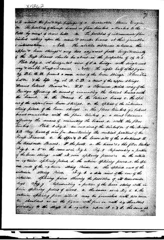
to be about the free & safe passage of a locomotive Steam Engine.
The positions of staple beams or floor timbers, attached to the Posts by means of screw bolts. The positions of intermediate floor timbers resting upon the main & counter braces, at their junction & intersection. Note: The relative distances between the upper & lower strings & any two adjacent posts longitudinally of the Truss Beams should be about in the proportion of 14 to 1.
Plate I Fig. 1. A horizontal view of a bridge with single road way & double Truss Beams. Note: The right half of this figure by B.C. & H. presents a cross view of the lower strings. The other half by the left fig. A.B.C.D. a view of the upper strings. Beams lateral Braces &c. B.E. a Staircase with way of the Bridge affording the means of connecting the lateral braces with the beams. a. the Beams b. the lateral braces c. the splices of the upper (and) lower strings. d. the splices of the intermediate string piece of the lower strings e. the floor timbers f. lateral braces connected with the floor timbers g. a short staircase affording the means of connecting the braces a. with the floor timbers.
Plate 2 Fig. 3. An end view of the timbers &c. of the Bridge. A.B. stay braces of iron for maintaining the vertical position of the Truss Beams. C. the upper & D the lower side of the abutment B. the transverse Braces. P the posts. a. the beams & c the floor timbers.
Fig. 4. a. E. &c the same as in Fig. 3. Fig. 5. Representing a portion of the lower string with its iron splicing pieces. a. the outside or exterior splicing pieces. b. the interior splicing pieces. c. the splice ends of the exterior string pieces. d. the splice ends of the interior string pieces.
Fig. 6. a side view of the end of the interior splicing pieces showing the position of its transverse lugs.
Fig. 7. Representing a portion of the lower string with interior splicing pieces of wood. a. the same as in Fig. 5. b. the interior splicing piece which may be furnished with two counter shoulders as in the figure, with four or with six shoulders according to the lugs to be erected upon it. c. & d. the same as in.
Page 5.
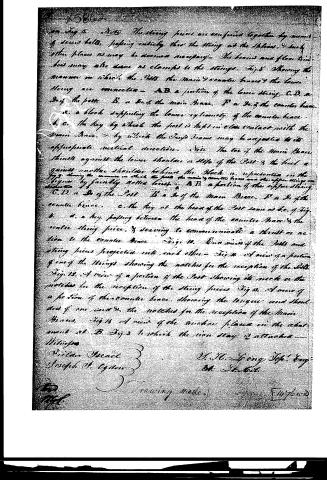
Fig. 5. Note: The string pieces are connected together by means of screw bolts, passing entirely thru the string at the bottom, & such other places as may be deemed necessary. The braces and floor timbers may also serve as clamps to the strings. Fig. 8. Showing the manner in which the Posts, the Main & counter braces & the lower string are connected. A.B. a portion of the lower string. C.D. a part of the post. B. a part of the main brace. P a part of the counter brace. a. a block supporting the lower extremity of the counter brace. b. c. the key by which the post is kept in close contact with the main brace, & by which the keys frame may be adjusted to its appropriate vertical direction. Note: The toe of the main brace thrust against the lower shoulder a step of the post & the heel against another shoulder behind the block a. represented in the Fig. 9. showing the manner in which the posts, the main & counter braces and the upper string are connected by firmly nailed keys. A.B. a portion of the upper string. C.D. a part of the post. B a part of the main brace. P a part of the counter brace. c. the key at the head of the post same as b.c. of Fig. 8. d. a key passing between the head of the counter brace & the center string piece, & serving to communicate a thrust or action to the counter brace. Fig. 10. End view of the Posts and string pieces projecting into each other. Fig. 11. A view of a portion of one of the strings showing the notches for the reception of the Posts. Fig. 12. A view of a portion of the Post showing its notch or the notches for the reception of the string pieces. Fig. 13. A view of a portion of the counter brace, showing the tongue and shoulders of one end & the notches for the reception of the main braces. Fig. 14. A view of the anchor placed in the abutment at B. Fig. 3 to which the iron stay is attached.
Witnesses
William Struck
Joseph H. Ogden
Y. H. Long, Sup't Eng'
Bk. St. Art.
Drawing made 147603
Published accounts: specification
Specification printed in the Journal of the Franklin Institute
Journal of the Franklin Institute, new ser., vol. 5 (1830), p. 231 · View the page
Text of the specification as printed in the Journal, from OCR; not proofread.
Specification of a patent for certain improvements in the construction of Wooden or Frame Bridges. Granted to S. H. LONG, Bt. Lt. Col. of the United States Engineers, March 6, 1830. THE objects aimed at in this invention, are greater simplicity and economy in the construction of bridges, together with greater strength and efficiency than have hitherto been attained from any combination of principles, or arrangement of parts heretofore adopted in structures of this description. The improvements under consideration, by means of which the objects above mentioned are to be accomplished, consist of the following modifications or arrangements, in the construction of the main longitudinal truss frames necessary to the formation and support of a bridge, viz. 1st. Two modes of splicing the string pieces, one of which is effected by means of wooden, and the other by means of iron splicing pieces of a construction different from any heretofore adopted in bridge architecture. 2nd. A system of bracing, by means of which the truss frames are exempted from leverage in every part liable to be affected by such an action, and the stresses or thrusts communicated by the braces, are resisted by shoulders or steps as nearly as may be at right angles with the grain, or fibres of the timber. S. H. LONG'S Wooden or Frame Bridges. 3d. A system of counterbalancing, by means of which the truss frames are rendered stiff and unyielding, and the bridge kept in uniform action, whether loaded or unloaded. 4th. A mode of furnishing the main braces and posts with metallic bearings, by the introduction of thin plates of iron, copper, or other suitable metal, between the heel and toe of each main brace, and the steps in the post against which they thrust, and 5th. A mode of keying, or wedging, by means of which the central parts of the truss frames, and consequently of the bridge, may be elevated, and sustained, in case of a subsidence or sinking of those parts, which is liable to happen from a shrinking and extraordinary compression of the timber. These several improvements which are claimed as new, useful, and original, together with a variety of other arrangements, many of which are believed to be unprecedented in bridge architecture, will be more clearly illustrated by the drawings and explanatory references hereto annexed, and exhibited 'under the designation of the "JACKSON BRIDGE." EXPLANATIONS AND REFERENCES TO THE DRAWINGS. Plate III. Fig. 1. A side view of a truss frame exhibiting the systems of bracing adverted to in articles 2nd and 3d of the preceding specification. A, B, the upper string showing the position of its splices, and the insertions of the posts, &c. C, D, the lower string with its splices, &c. Note. Inasmuch as the upper string acts by thrust, and the lower by tension, the splices of the latter only require particular care and precision in their adjustment. E and F, inferior arch braces, supported on the lower sill of the abutments, and inserted in the lower string immediately behind the 2nd and 3d posts from each extremity of the truss frame. G, superior arch braces connected with the centre post prolonged above the frame, and inserted in the upper string, at the head of the 2nd post from the centre. a, the posts, b, the main braces, c, the counter braces. Note. This figure is also intended to indicate the manner of constructing the Carrolton viaduct, which differs from the bridge only in its adaptation to the purposes of a rail-road, in which application the floor timbers must be more frequent in order to afford an unyielding support to the rails, and the arrangements in other respects must be such as to admit the free and safe passage of a locomotive steam engine. m, the positions of clamp bearers or floor timbers, attached to the posts by means of screw bolts. n, the positions of intermediate floor timbers resting upon the main and counter braces at their junction and intersection, upper and lower. Note. The relative distances between the strings and any two S. H. LONG'S Wooden or Frame Bridges. adjacent posts longitudinally of the truss frame, should be about in the proportion of 1 to 1. Fig. 2. A horizontal view of a bridge with single road-way and double truss frames. Note. The right half of this figure, viz. BC, GH, presents a view of the lower strings, floor timbers, &c., and the left, viz. ABCD, a view of the upper strings, bearers, lateral braces, &c. E, F, a streamer, midway of the bridge, affording the means of connecting the lateral braces, with the bearers. a, the beams, b, the lateral braces, c, the splices of the upper and lower strings, d, the splices of the interior string piece of the lower strings, e, the floor timbers, f, lateral braces connected with the floor timbers, g, a short streamer affording the means of connecting the braces, e, with the floor timbers. Plate IV. Fig. 3. An end view of the timbers, &c. of the bridge. AB stay braces of iron, for maintaining the vertical position of the truss fames. C the upper and D the lower sill of the abutment. E the transverse braces. F the posts. a, the beams, and e, the floor timber. Fig. 4. a and e, the same as in Fig. 3. Fig. 5. Representing a portion of the lower string with its iron splicing pieces, &c. a, the outside or exterior splicing pieces, b, the interior splicing pieces, c, the spliced ends of the exterior string pieces, d, the spliced ends of the interior string pieces. Fig. 6. A side view of one of the interior splicing pieces showing the position of its transverse lugs. Fig. 7. Representing a portion of the lower string with interior splicing pieces of wood. a, the same as in Fig. 5, 6, the interior splicing piece, which may be furnished with two counter shoulders, as in the figure, with four or with six shoulders, according to the stress to be exerted upon it. cand d the same as in Fig. 5. Note. The string pieces are confined together by means of screw bolts, passing entirely through the string at the splices and such other places as may be deemed necessary. The beams and floor timbers may also serve as clamps to the strings. Fig. 8. Showing the manner in which the posts, the main and counter braces, and the lower string are connected. A, B, a portion of the lower string. C, D, a portion of the post. E, a portion of the main brace. F, a portion of the counter brace. a, a block supporting the lower extremity of the counter brace, b, c, the key by which the post is kept in close contact with the main brace, and by which the truss frame may be adjusted to its appropriate vertical direction. 14 Note. The toe of the main brace thrusts against the lower shoulder or step of the post, and the heel against another shoulder behind the block, a, as represented in the figure. VOL. V. No. 4.-APRIL, 1830. 30 1 S. H. LONG'S Wooden or Frame Bridges. Fig. 9. Showing the manner in which the posts, the main and counter braces, and the upper string, are connected. A, B, a portion of the upper string. C, D, a portion of the post. E, a portion of the main brace. F, a portion of the counter brace. c, the key at the head of the post, same as b, c, of Fig. 8. d, a key passing between the head of the counter brace and the centre string piece, and serving to communicate a thrust or action to the counter brace. Note. The string pieces, in this and the preceding figures should be so adjusted that the toes of the main braces will be situated at the centres of the former, and their heels at least three inches above the string pieces. Fig. 10. End views of the post and string pieces projected into each other. Fig. 11. A view of a portion of one of the strings showing the notches for the reception of the posts. Fig. 12. A view of a portion of the post showing its neck, or the notches for the reception of the string pieces. Fig. 13. A view of a portion of the counter brace showing the tongue and shoulder of one end; and the notches for the reception of the main braces. Fig. 14. A view of the anchor placed in the abutment at B, Fig. 3, to which the iron stay is attached. Some remarks on the foregoing, by the Patentee. TO THE EDITOR OF THE JOURNAL OF THE FRANKLIN INSTITUTE.. SIR,-I take the liberty to offer for publication, in your valuable Journal, a description of the Jackson Bridge, together with drawings explanatory of the manner of its construction, and of the adjustment of its parts. The only bridge hitherto constructed on this plan, has lately been built on the Washington road, about 24 miles from Baltimore, at its intersection with the Baltimore and Ohio Rail-road, and at an elevation 40 feet above the latter. The length or span of the bridge is 109 feet, its width from out to out 24 feet, and its height from bottom to top of its posts, 14 feet. It is supported by a double truss frame on each side, furnished with arch braces beneath only; the upper arch braces not being required in a bridge of that length. The exterior string pieces of each string are only six inches square, and the interior six by eight inches. The posts at the ends, and at the centre of the bridge, as also the arch braces, are of the size last mentioned. The other posts, and the main braces, are six inches square. The counter and lateral braces are only five inches square. The whole of the timber, except the keys, is white pine, with no other seasoning than what it might have acquired in six weeks, during which time the work was in progress, having been framed and raised in that time by six workmen only. Independently of the abutments and exterior covering of the bridge, its cost, inclusive of materials and workmanship of every kind, was only about eleven hundred dollars. However slender the materials of which this bridge is composed, and however deficient in strength it may appear, it is crossed daily by stages at full speed, and has actually sustained about eighty beeves, driven across it at once, in close gang, without the least apparent yielding in the truss frames. Agreeably to the most approved rules for computing the strength of similar structures, it will sustain, on every square foot of its floor, in addition to its own weight, at least 130 pounds, or equally distributed over the entire surface of its floor, about one hundred and ten tons weight. Very respectfully, yours, &c. S. H. LONG.
Published accounts: journal notice
Notice in the monthly list of patents
Journal of the Franklin Institute, new ser., vol. 5 (1830), p. 231 · View the page
It consists of a windlass standing across the press from one cheek to the other; this is to be turned by a handspike, there being a ratchet wheel and catch to prevent it from turning back. A rope from each end of the windlass passes round sheeves in the sliding frame. There are three represented in the drawing, but a greater number, it is stated, may be used; this windlass, with its tackles, operates upon the follower of the press, and draws it up, or down, according to the arrangement made. SPECIFICATIONS OF AMERICAN PATENTS. Specification of a patent for certain improvements in the construction of Wooden or Frame Bridges. Granted to S. H. LONG, Bt. Lt. Col. of the United States Engineers, March 6, 1830.
Published accounts: journal notice
Notice in the monthly list of patents
Journal of the Franklin Institute, new ser., vol. 5 (1830), p. 364 · View the page
9. For a Wooden, or Framed Bridge; S. H. Long, Baltimore, Maryland, March 6.
About this record
- Patentee
- DATAMP
- Date
- the Name and Date index of patents, DATAMP, USPTO records
- Invention
- DATAMP
- Listed in
- the Name and Date index of patents, DATAMP, USPTO records, Jim Shaw's X-patent list, the Journal of the Franklin Institute, Burke's List of Patents (1847)
- Burke's 1847 Patent Office list gives the same patent.