

Drawings and documents
USPTO scan
The patent as scanned by the USPTO
-
 Page 1
-
 Page 2
-
 Page 3
-
 Page 4
-
 Page 5


U.S. Patent and Trademark Office · Google Patents
Show the transcription Hide (1,189 words)
Machine transcription (LightOnOCR) of the pages as scanned by the USPTO, most of them the handwritten copies made when the records were restored after the 1836 fire. Not checked; it can misread handwriting, so compare it with the scan.
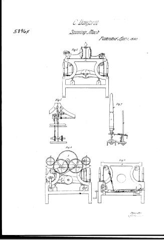
Page 1.
5896X
C. Danforth
Spinning Mach
Patented Apr. 1, 1830.
Fig 1
Fig 5
Fig 7
Fig 3
Fig 4
Transmitted
Page 2.
No Printed Specification Available
C. Danforth
5896X
Spinning Mach.
Patented Apr. 1, 1830.
Sheet 2, 2 Sheets
Inventor
C. Danforth
Page 3.
April 15, 1809
Charles Danforth of Patterson, New Jersey
Inventor.
The subscribers referred to in their Letters Patent, and nothing but of the same containing a description in the words of the said Charles Danforth himself of his improvement in the Spinning machine, commonly known by the name of Danforth's Patent Throttle.
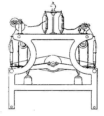
To all whom these presents shall come, We it known that Charles Danforth of Patterson in the County of Essex and State of New Jersey have invented a new and useful improvement on a Spinning machine for Spinning Cotton, commonly known by the name of Danforth's Patent Throttle, for which invention he obtained Letters Patent September 27th A.D. One thousand Eight hundred and twenty eight, under the name of the Immovable flyer, and that the following is a full and exact description of the said improvement as invented by him. It consists of an improvement by which the cylinder made use of for driving the rollers or Bobbins, instead of revolving on fixed or stationary bearings, is made to traverse with the traverse rails & rollers, whereby the tension of the bands is kept the same when the rails are up in the centre or at the bottom. It also consists in dropping or lowering the roller and Bobbin for the convenience of piecing or winding the broken ends or threads. This invention or improvement I call the traversing cylinder and drop bobbin. The cylinder is made to traverse by the same apparatus which gives motion to the rails, instead of having the cylinder bearings fastened to the ends of the frame as is the case on the ordinary Throttle. There is a bar of cast iron running across the frame from one traverse rail to the other, the ends of this bar are bolted fast to a flange on the end of the traverse rails. There is a bar of this kind at each end of the traverse rails, in the centre of which bars the bearings for the journals of the cylinder are fixed, so that as the rails rise and fall the cylinder rises and falls with them. The arrangement for moving or traversing the cylinder is as follows, viz. There is a shaft or arbor between rollers long by one and a quarter inch diameter, connected to bearings four inches back of the front of the frame, another roller from the centre of the frame, and about two inches below the centre of the cylinder.
Page 4.
when the cylinder and rails are in the center of their socket or when the bottom is half full. This shaft runs parallel with the cylinder, to which shaft is firmly fixed two straws or arms in an upright position about ten inches long and of a size sufficient to prevent the staff of the belt from springing them; at the top of these stands are fixed bearings for a counter or driving shaft. This shaft it will be seen runs parallel with the cylinder and is on a level with it when the cylinder as before stated, is in the center. On the end of this counter shaft on the front end loose pulleys by which motion is communicated to the whole machine, and on the other is a pulley that gives motion to the cylinder by a belt running from said pulley round a pulley on the end of the cylinder. The rollers are turned by this same counter shaft by means of a belt or gearing. There is a connecting or festoon rod, running from the cylinder journal to the journal of this counter shaft, having a hub on each end; these hubs are perforated or drilled thro' which the journal of the cylinder and the journal of the counter shaft passes. These hubs serve as a bearing for the cylinder journal at one end, and for a bearing for one end of the counter shaft. The outside surface of these hubs are turned and grooved out to suit a socket and cage box in the cage box and on one of the stands above written of. The use of this connecting or festoon rod is to steady the counter or driving shaft and to keep it always the same distance from the cylinder, so that the cylinder belt will be of the same tightness when the rails are up as when the rails are down. The apparatus for dropping the wales and bobbins is as follows, viz: The traverse rails, instead of traversing on the spindle or having the spindle pass thro' them (as is the case with the ordinary kind) are placed about three inches back of the spindle. The rails are made of cast iron about three inches wide, and about a quarter of an inch thick having a rib or stiffener on the backside about one inch deep. On the front is a rib about one sixteenth of an inch deep for the brass counter spoken of to rest against. The levers are made of rolled iron about three quarters of an inch wide and about one eighth of an inch in thickness. They are long enough to extend from the back rib or stiffener on the rail to about half an inch in front of the spindle. They are placed to the same end of the traverse
Page 5.
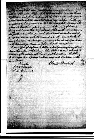
made by means of a bolt about three inches long and one quarter of an inch diameter, passing thro' the front of the cylinder and a hole in iron near the anterior of the lever made for the purpose. On this bolt is a spiral spring made of about number eight iron wire about one and half inch long. This spring is regulated by a nut screwed on the bottom of said bolt. The use of this spring is to keep the lever hard up against the lower side of the nails. There is a slot made thro' the front end of the lever thro' which the spindle and the rollers which run on the spindle rest on this lever and of consequence to move with the lever and nails. When one end breaks, this lever is forced down the spiral spring and doing when the end being obtained the lever is let go, it returns to place and the end is fixed. The same effect of stopping the bobbin is done by means of a weight and lever, that is done with a spring. What I claim as my invention is the harnessing of the cylinder with the nails and the stopping the bobbin for the convenience of peering in all and every mode whatsoever on the above throttle.
Charles Danforth
1846
Witnesses
J. W. H. Minnie
S. M. Grismond
Published accounts: journal notice
Notice in the monthly list of patents, with remarks
Journal of the Franklin Institute, new ser., vol. 6 (1830), p. 1 · View the page
1. For an improvement on a Machine for Spinning Cotton, known by the name of "Danforth's Patent Throstle;" Charles Danforth, Patterson, New Jersey, April 1.
Remarks. The machine upon which this is an improvement, was patented September 2nd, 1828, and in our list is denominated an " Improvement in the Construction, Manufacture, and management of the Bobbins and Flyers for Spinning Cotton." We did not publish any account of the plan of this apparatus at the time, from the wish of the patentee that it might be delayed, as he then contemplated securing his right in Europe, which a publication here might have defeated. On the 31st of March, 1828, a description of some improvements in spinning was received at the patent office, from Mr. John Thorp, of Providence, Rhode Island, and a patent for these improvements was subsequently obtained by him. The description referred to will be found at page 41, of the last volume. The patent obtained by Mr. Danforth, in September, 1828, was for an improvement bearing a strong resemblance to that described, and afterwards patented by Mr. Thorp; Mr. Danforth has obtained the present patent for a further improvement on his first mode. We shall not attempt to enter into particulars respecting the arrangement devised by Mr. Danforth; its general object will be understood by the reVOL. VI. No. 1.-JULY, 1830. 1 ference already made; more would require drawings. The question of who was the first inventor is one which we are not prepared to discuss, as it belongs to another tribunal.
DATAMP: illustration
Illustrations from DATAMP
DATAMP (Directory of American Tool and Machinery Patents), via the Internet Archive · Archived DATAMP page
About this record
- Patentee
- DATAMP
- Date
- the Name and Date index of patents, DATAMP, USPTO records
- Invention
- DATAMP
- Listed in
- the Name and Date index of patents, DATAMP, USPTO records, Jim Shaw's X-patent list, the Journal of the Franklin Institute, Burke's List of Patents (1847)
- Burke's 1847 Patent Office list gives the same patent.