

Drawings and documents
National Archives restored drawings: drawing
Israel Overall's Patent Drawing for a Machine for Boring Rock

National Archives, Restored Patent Drawings (Record Group 241) · Full-size scan at the National Archives · Catalog record
Show the text on the drawing Hide (134 words)
Words on the drawing as machine-read by the National Archives; not checked. Useful mainly for searching.
DIV. 15 / $150 / Israel Overall / Machine for boring Rocks. / Vol. io pg. 451. / 5932. X / Patented april 23. 1830. / Preferences. a a side posts. b. the sill C the cap. d.d the mortices. / Jig. i. / e the anger driver. of the anger 02 bit g the wrench. / h the top spring. i the lower springs or side springs. K.K. the guides / l.l. fr. holes to regulate the springs. m m the Top supports. n.n bottom supports. / o. the guide. p vessel containing water g the channel to let the water in the lock. 0 Sig. 2 annother mode / for making the springs. e the driver. / Tig.1. / OIR / Patent affice / the direction of the Commissions / of Patents in informity 1857 / the / MLSUmorth / Commisions af Intents.
USPTO scan
The patent as scanned by the USPTO
-
 Page 1
-
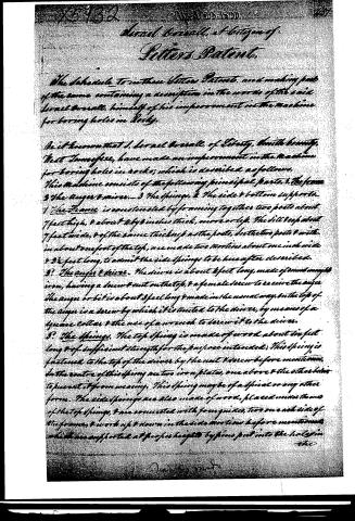 Page 2
-
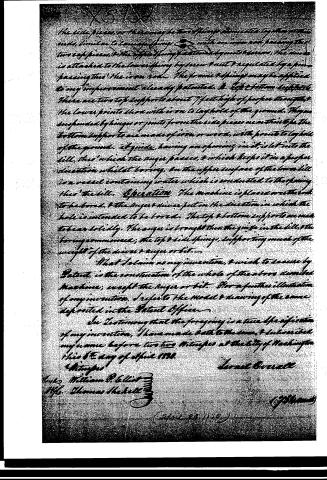 Page 3


U.S. Patent and Trademark Office · Google Patents
Show the transcription Hide (781 words)
Machine transcription (LightOnOCR) of the pages as scanned by the USPTO, most of them the handwritten copies made when the records were restored after the 1836 fire. Not checked; it can misread handwriting, so compare it with the scan.
Page 1.
5932X
J. Overall.
Boring Artesian Wells.
Patented Apr. 23, 1830.
NO PRINTED COPY OF SPECIFICATION IN OFFICE.
Fig. 1

Fig. 2.

Page 2.
X5732 April 23 1820 467
Lornel Overall, a Citizen of
Letters Patent.
The schedule to in these Letters Patent, and making part
of the same containing a description in the words of the said
Lornel Overall, himself of his improvement in the machine
for boring holes in Rocks.
Be it known that I, Lornel Overall, of Liberty, Smith County,
West Tennessee, have made an improvement in the machine
for boring holes in rocks; which is described as follows.
This machine consists of the following principal parts, 1. The frame
2. The auger & driver. 3. The springs. 4. The side & bottom supports.
1. The Frame is constructed by framing together two posts about
7 feet high, & about 4 by 8 inches thick, more or less. The sill being about
7 feet wide, & of the same thickness as the posts, in the two posts & with
in about one foot of the top, are made two mortises about one inch wide
& 5 1/2 feet long, to admit the side springs to be hereafter described.
2. The auger & driver. The driver is about 2 feet long, made of round maple
iron, having a screw & nut on the top, & a female screw to receive the auger
The auger or bit is about 3 feet long & made in the usual way, on the top of
the auger is a screw by which it is united to the driver, by means of a
square collar & the use of a wrench to screw it to the driver.
3. The springs. The top spring is made of wood about 6 feet
long & of sufficient strength for the purpose intended; This spring is
fastened to the top of the driver by the nut & screw before mentioned.
In the centre of this spring are two iron plates, one above & the other below
to prevent it from weaving. This spring may be of a spiral or any other
form. The side springs are also made of wood, placed under the ends
of the top spring, & are connected with four guides, two on each side of
the frame, & work up & down in the side mortises before mentioned,
which are supported at proper heights by pins set into the holes in the
Lornel Overall
Page 3.
The side pieces, or there may be two springs connected together in one end, similar to a hinge spring, with an iron rod passing through two of the pieces, the upper spring is attached by means of screws, the iron is attached to the lower spring by screw and nut & regulated by a pin passing through the iron rod. The frame & springs may be applied to any improvement already patented.
In Left & Bottom Left Side:
There are two top supports about 7 feet high of proper strength, the lower points show with iron to lay hold of the ground. They are suspended by hinges or joints from the side pieces near their tops. The bottom supports are made of iron or wood, with points to lay hold of the ground. A guide, having an opening in it, is let into the sill, thus which the auger passes, & which keeps it in a proper direction whilst boring. On the upper surface of the lower sill is a vessel containing water which is conducted to the spring thus the sill.
Operation: The machine is placed over the hole to be bored, & the auger & driver put in the direction in which the hole is intended to be bored. The top & bottom supports are made to bear solidly. The auger is brought thru the guide in the sill, & the boring commenced; the top & side springs, supporting much of the weight of the driver & auger or bit.
What I claim as my invention, & wish to secure by Patent, is the construction of the whole of the above described machine; except the auger or bit. For a further illustration of my invention, I refer to the Model & drawing of the same deposited in the Patent Office.
In Testimony that the foregoing is a true specification of my invention, I have made both to the same, & subscribed my name before two witnesses at the City of Washington this 8th day of April 1830.
Witnesses
Lys William P. Gellatly
Wm. Thomas Shekell
Israel Dorrall
Filed April 20, 1830
Published accounts: journal notice
Notice in the monthly list of patents, with remarks
Journal of the Franklin Institute, new ser., vol. 6 (1830), p. 13 · View the page
37. For a Machine for Boring Holes in Rocks; Israel Overall, Liberty, Smith county, Tennessee, April 23.
Remarks. A frame is made consisting of a sill, two uprights, and a cap piece, so as to resemble a frame for a door, or gate; an auger is fitted into a socket in an iron rod, called the driver, this is placed to stand vertically in the middle of the frame, the sill being perforated to allow the shank of the auger to pass through it, and the upper end of the driver being secured in its position by means of a screw and nut, which affix it to a wooden spring, running along under the cap piece of the frame, and extending its whole length; this spring is so attached at its ends to elastic sliding pieces, that it may be lowered by means of slots in the uprights, and follow the auger as it descends; pieces called supports, are attached to the frame to set and keep it upright. The claim is to "the construction of the whole of the above described machine, except the auger, or bit."
About this record
- Patentee
- DATAMP
- Date
- the Name and Date index of patents, DATAMP, USPTO records
- Invention
- DATAMP
- Listed in
- the Name and Date index of patents, DATAMP, USPTO records, Jim Shaw's X-patent list, the Journal of the Franklin Institute, Burke's List of Patents (1847)
- Burke's 1847 Patent Office list gives the same patent.