

Drawings and documents
USPTO scan
The patent as scanned by the USPTO
-
 Page 1
-
 Page 2
-
 Page 3


U.S. Patent and Trademark Office · Google Patents
Show the transcription Hide (945 words)
Machine transcription (LightOnOCR) of the pages as scanned by the USPTO, most of them the handwritten copies made when the records were restored after the 1836 fire. Not checked; it can misread handwriting, so compare it with the scan.
Page 1.
UNITED STATES PATENT OFFICE
PTO – BOYERS, PA DUTY STATION
PAGE NOT AVAILABLE
PATENT NUMBER X5937 FOR THE ISSUE DATE
4/27/1830 HAS BEEN SCANNED/LOADED, BUT WITH MISSING PAGE(S). UPON RECEIPT OF THE MISSING PAGE(S), THE ENTIRE DOCUMENT WILL BE RESCANNED. THIS NOTICE IS FOR THE MISSING PAGE CONTAINING:
Missing All Drawings
DATA CONVERSION OPERATION
BOYERS, PA
Page 2.
X5937
U.S. 27.1830
399
Benjamin Winkley
Letters Patent.
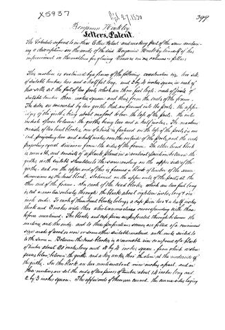
We include referred to in this Letters Patent and making part of the same containing a description in the words of the said Benjamin Winkley himself of his improvement in the machine for gluing Vessels on columns & pillars.
This machine is sustained by a frame of the following construction viz. two sills of suitable timber, two and a half feet long, and 3 by 4 inches square, in each of these sills set the feet of two posts, which are three feet high, made of joists of suitable timber three inches square and thus form the ends of the frame. The sides are connected by two girts that are framed into the posts, the upper edges of the girts being about one foot below the top of the posts. The intermediate space between the girts being two and a half inches. The machine consists of two head blocks, one of which is fastened on the top of the posts in one end, projecting two and a half inches over the outside of the posts, and the ends projecting equal distances from the sides of the frame. The other head block is moveable, and consists of a plank placed in a vertical position between the girts, with suitable shoulders to the same resting on the upper side of the girts, and on the upper end of this is framed a block of timber of the same dimensions as the head block, stationed on the upper ends of the posts at the other end of the frame. In each of the head blocks, which are two feet long is cut a mortise entirely through the block about eighteen inches long & one inch wide. To each of these head blocks belongs a cap piece two & a half inches thick and 3 inches wide, that which has mortises corresponding with those before mentioned. The blocks and cap pieces are perforated through between the mortises and the ends, and to these perforations screws are fitted of a convenient size made of wood or iron or some other suitable material with nuts suited to the same. Between the head blocks is a moveable vice composed of a block of timber about 20 inches long and 3 by 4 inches square, from which a stem passes below, between the girts, and a key works thro' the slot at the underside of the girts. In this block are two mortises about nine inches apart, and in these mortises are set the ends of two pieces of timber about 14 inches long and 2 by 3 inches square. The upper ends of these are curved, the convex sides laying
Page 3.
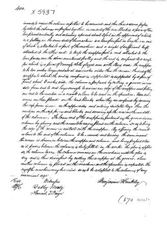
inwards to receive the column or pillar to be veneered, and thro' these a screw passes by which the columns are prefixed together. In one end of the vice block is a piece of iron bar placed vertically and extending upward about 3 feet in the upper end of which is a pulley. On the same side of the machine is a lever five feet in length, one end of which is attached to a post of the machine, and a weight of sufficient heft attached to the other end, to keep the wrapper fast. A cord attached to the lever passes over the above mentioned pulley and the end is confined to a wrapper which is a piece of canvas cloth glazed over with bees wax. The wrapper to be two inches longer and about six inches wider than the veneer. The end of the wrapper to which the cord is confined is supported by a piece of board about 3 inches wide. The column is prepared by cutting a groove in one side from end to end large enough to receive one edge of the wrapper and fitting one end to the mortise in a crank or lever to be used in the operation. Two columns are then placed on the head block, when they are confined by securing the cap pieces in iron, on the upper sides and entering suitable keys thro' the mortises in the cap pieces and blocks and screwing up the vice in the middle of the columns. The lower end of the wrapper is fastened in the groove in one column by gluing and the veneer to be used is placed on the column so as to bring the edge of the veneer in contact with the wrapper. By affixing the crank or lever to the end of the column to be veneered and turning the same inward the veneer is drawn in between the wrapper and column and being prefixed slow as it passes between the columns is duly fitted in the work. The glue is applied as the column turns. The column remains in the machine until the glue is dry and is then disinfixed by cutting the wrapper at the groove, when another column is placed in the machine and the operation is repeated. The size of the machine may be varied so as to be adapted to the columns of any convenient size.
Benjamin H. Mitkley
(870 words)
Published accounts: journal notice
Notice in the monthly list of patents, with remarks
Journal of the Franklin Institute, new ser., vol. 6 (1830), p. 16 · View the page
(Specification in the next number.) 43. For a machine for Glueing Veneers on Columns or Pillars, to be used in cabinet work; Benjamin Hinkley, Fayette, Kennebeck county, Maine, April 27.
Remarks. The column which is to be veneered, is to be fixed in a frame, where it is held by screws, but so loosely that it may be turned round, by a cross bar, or crank, affixed to one of its ends. A waxed cloth, somewhat longer and wider than the veneer to be laid, is held in a vertical position, its lower edge being glued into a groove made along the column, and its upper edge fastened to a strip of wood. It is strained tight, by a rope passing from this strip, over a pulley, and acted on by a lever and weight. The veneer is placed against this cloth, its edge resting on the column, glue is then applied, and the column turned, the glueing being continued until the whole is wrapped round. The cloth is so managed as to strain tightly, and close the veneer to the column; it is then left until the glue is sufficiently hardened to take it from the machine, when the cloth is cut off; leaving a strip of it in the groove. The description of this machine is elaborate, but not clear, the drawing which accompanies it is sufficiently well executed, but is without written references.
About this record
- Patentee
- DATAMP
- Date
- the Name and Date index of patents, DATAMP, USPTO records
- Invention
- DATAMP
- Listed in
- the Name and Date index of patents, DATAMP, USPTO records, Jim Shaw's X-patent list, the Journal of the Franklin Institute, Burke's List of Patents (1847)
- Burke's 1847 Patent Office list gives the same patent.