

Drawings and documents
National Archives restored drawings: drawing
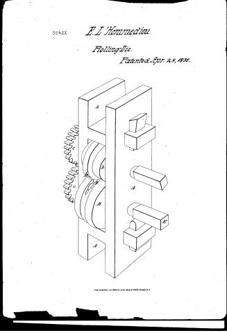
E. L. Hommedieu's Patent Drawing for Shaping Hammers, Spike-Gimblets, and Augers

National Archives, Restored Patent Drawings (Record Group 241) · Full-size scan at the National Archives · Catalog record
Show the text on the drawing Hide (69 words)
Words on the drawing as machine-read by the National Archives; not checked. Useful mainly for searching.
pise / E. o IL' HOMMIEDIEU / 5942+ / for Shaping spike.gimblets, augersee / Patented 28th april 1830 / A. Frame or clamp / B. Roll grooved. b. Tongued Roll / C. Spur wheels / D. Die. / E. Driving shaft / A. / Patent affir GS-25,1838 / Made under the derection of the Cormipine / of Patents in conformity with act of March (183) / Commissioner of Patents,
USPTO scan
The patent as scanned by the USPTO
-
 Page 1
-
 Page 2
-
 Page 3


U.S. Patent and Trademark Office · Google Patents
Show the transcription Hide (584 words)
Machine transcription (LightOnOCR) of the pages as scanned by the USPTO, most of them the handwritten copies made when the records were restored after the 1836 fire. Not checked; it can misread handwriting, so compare it with the scan.
Page 1.
5942X
E. L'Hommedieu.
Rolling-Die.
Patented Apr. 28, 1830.

THE GRAPHIC CO. PHOTO-LITH. 39 & 41 PARK PLACE, N.Y.
Page 2.
X 5942
Ozra. S. H. Commodius
Letters Patent.
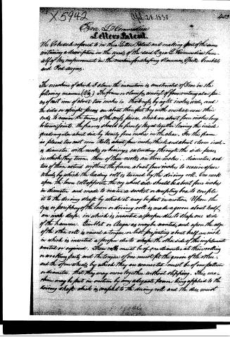
The Schedule referred to in this Letter Patent and making part of this same containing a description in the words of the said Ozra S. H. Commodius himself of his improvement in the machine for shaping Hammer, Spike, Gimblet, and Rod Augers.
The machine of which I claim the invention is constructed of Iron in the following manner (Fig.) The frame or clamps consist of four rectangular pieces of cast iron of about two inches in thickness by eight inches wide, and the sides or upright pieces are about three feet long with notches near their ends to receive the tenons of the cross pieces, which are about four inches long between joints. The frames should be firmly keyed together leaving the inside quadrangular about six by twenty-four inches in the clear. On this frame is placed two cast iron Rolls about four inches thick and about eleven inches in diameter, with necks or bearings extending through the side pieces in which they turn. Three of these necks are three inches in diameter, and two of them extend without the frame about four inches to receive four wheels by which the leading roll is turned by the driving roll. One neck upon the lower roll opposite the cog wheel side should be about four inches in diameter and made to receive a socket or coupling box to couple it to the driving shaft by which it may be put in motion. Upon the eye or periphery of the lower or driving roll is made a groove about half an inch deep, in which is inserted a proper die to shape one side of the hammer, Gimblet or Auger as maybe wanted, and upon the edge of the other roll is raised a tongue or list projecting about half an inch in which is inserted a proper die to shape the other side of the implement wanted or required. These rolls must be of one diameter at their rolling or working parts and the tongue of one must fit the groove of the other, and the four wheels by which they are connected must be of one pattern or diameter, that they may move together without slipping. This machine may be put in motion by any adequate power being applied to the driving shaft which is coupled to the driving roll and the dies must
Page 3.
X5949
being placed in the rolls, and rolls of paper are passed through which will shape a piece of hot iron or steel into the required form on them into the form desired. By this machine much time and labor may be saved in shaping the above mentioned articles. I claim that the application of the above described machine to shaping the articles so far said is my discovery and for which I shall claim Letters Patent.
For a further illustration of the machine I refer to the drawing accompanying this Specification.
In testimony whereof I have hereunto set my hand and seal this 21st day of January A.D. 1830.
Cert. Witnesses
M.H. Samuel Strong
Phoebe Clarke
Cyra L. Hommedieu
(Patented April 26, 1830)
Published accounts: journal notice
Notice in the monthly list of patents, with remarks
Journal of the Franklin Institute, new ser., vol. 6 (1830), p. 16 · View the page
For one of its relatives, see No. 15; the family is very large. 45. For a Machine for Shaping Hammers, Spike Gimlets, and Pod Augers; Ezra L'Hommedieu, Saybrook, Middlesex county, Connecticut, April 28.
Remarks. This machine consists of steel rollers mounted in the manner of flatting mill rollers; their surfaces are to be so cut as to form dies for giving the proper shape to the hammers, gimlets, or augers. The claim is to "the application of the above described machine, to shaping the articles aforesaid, as my discovery." It had been previously discovered that nails, screws, spoons, forks, &c. &c. &c. might be formed in the above way. We very much doubt the possibility of sustaining a patent for every individual article which may be made by a well known method, as we cannot in such a case perceive either invention or discovery. If I want a piece of iron forged into a particular form, and the smith executes it with his hammer, anvil, and tongs, can I claim a patent for these as applied to forging iron into that form? Among the various machines similar to this, is that of Mr. Davis, noticed vol. v. p. 159, for making nails, bolts, screws, &c. by rollers.
DATAMP: illustration
Illustrations from DATAMP


DATAMP (Directory of American Tool and Machinery Patents), via the Internet Archive · Archived DATAMP page
About this record
- Patentee
- DATAMP
- Date
- the Name and Date index of patents, DATAMP, USPTO records
- Invention
- DATAMP
- Listed in
- the Name and Date index of patents, DATAMP, USPTO records, Jim Shaw's X-patent list, the Journal of the Franklin Institute, Burke's List of Patents (1847)
- Burke's 1847 Patent Office list gives the same patent.