

Drawings and documents
National Archives restored drawings: drawing
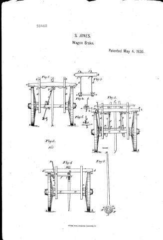
Rogers and Turman's Patent Drawing for Improvements to Jones Waggon Lock


National Archives, Restored Patent Drawings (Record Group 241) · Full-size scan at the National Archives · Catalog record
Show the text on the drawing Hide (775 words)
Words on the drawing as machine-read by the National Archives; not checked. Useful mainly for searching.
Sheet 1. 21. CARRIAGES & WAGONS. / [31] Brakes. / 1/250 / Rogers and Fruman of admin of Samuel Jones Patented May 4th 1830 / Patented / prestore a Plost / wr / you / 5946-+ / sig 3 / you / Nou / Fight / №1 / Seale 20 parts tie / Fight Tig / №5 / tommed / Hig-6 / Юроц / pig 5 / References to "Tonis Naggon Joch" No, Sig /. / Refermers 't' 4. Fig 3 in / ee Inition Barr / ab two hindWhuts of the Haggon 0 Pm through the shaft nn 10 / aa Section of the shape / bb sution of ther friction bay / f.g. the eye Senw bott through frition / CC Hard bolster with aple it fashni on ther haver / bar. on the end at f. the / ddi section of the lower burails pp eye botto in which the shaft / ce two shaft eye paping through / the shaft. / turns having burs sensed / dd Connecting rods with eyes at ce / h the cham attatchic to the eye / eye at I' / " Hind Hormas / ee / Burrs on the ends of thaft eye botts / bott and Tothe up in the roacinn / If a Section of the coupling pole the ends / gg / ffff one wingid nuts / the rod of drow / waist piece / 22 two rollers on the shaft on / Heg 4 / R the swivil through which the / hh Printion Bar / sod is inserted / which the connecting chains / aa Sution of the shaft / ii Initim blocks fastened in / bcd. a hook on one end of ther conna / I.m. the serve pin, through the Imall / wind when the shaft is timed in / their notehes the frietion has / applying the friction Toth Whits / =ecting rod / end of which at lis a Ray / n. / the Denner ptate / RR banas on the ends of Fristion bar rr connecting chames or rods / the Rey which paper through the 0 / ll Revits through fruttin bar / eye / botts / attatched / Toth / end of hook on the connisting row / the crank fastned on ther and / con / min sping fixed to from has / fg the shape eyabott with aburr / of the service per at may / - neating chaines having jouts / a Rey through it / n shaft of the Maggon lock / at g. / at and I one mmy nuts at & / pig. / pp. a Section of the coupling / pole / on the end of eye boths / aa Section of the shaft / им The leaver / bed a horkedbott with a th / q.r. / trop of Ison with the anti / Fig I soller in nil / end / and / r the leaver chain attalched to / key / through / the / hooh / fretion iron it at q / of / at / the / mar b. / A the hook on the soller / w. the hook, in the fornt sice of / forward side of the botster / the friction bas, to hitch the lean / section of the connicting rod / through which the sensor / with an up through which / pin is inserted / chana When the frature blocks / the hooh is inserted / am applyed tothe whits / Nos Pig be / tttt Burrs on the end of staptes / through the bedralls which / XXXX burs on the and of staptes / a CC b. the two hind where of haggon / the hind bolster with and under is / confin the frution bar to ets / the fretion banto its plan / on the bed ralls which confin / plan / dd Sections of lower bed mils
Sheet 2. CLASSIFICATION / 5946 1001 + / DIVISION. / Pig / Seale 4 parts to an inch / Nob / Pigz / C' / Seal 20 parts to an inch / No b Piy 7 / n the burn on the man and / ab the two him whiles / of the shaft to confine the / CC the botster of axh under it / da Pretion buy / washer sag cylinous rag / what and hand lever / ll Section ofthe lowerbearnes / to thin places. / f the shaft / Fig 8 / of the eye both with burn / The hand liarer including / on the end below the coupting / the band of Boy with / pole through which thefar / the sping GD fastmed / end of the shaft is inserted / and a bun senud on the and / senio at E and all / on the perphing by a / of the shaft; against this / eye bott the pinion works / enclosing the mag my linan / in the rach / The hole through the rag / hi the rach through the chftin / cylmair one end of which / is her ep hibited / it at h is a pin and a Rey / through the pin at h / The Stop confined in its / R The end of the Senwbott / plan by the sping CD / with a burr on it through / the eye of which at hisa pin / / spike in the Coupting pola / M. The mag what / n The clien / 0 the rug cylinary / p q. The hand lever including / the band & Boy boths / over one end of the rag eyes / =mair at I
USPTO scan
The patent as scanned by the USPTO
-
 Page 1
-
 Page 2
-
 Page 3
-
 Page 4
-
 Page 5
-
 Page 6
-
 Page 7
-
 Page 8
-
 Page 9
-
 Page 10
-
 Page 11
-
 Page 12
-
 Page 13
-
 Page 14
-
 Page 15
-
 Page 16
-
 Page 17
-
 Page 18
-
 Page 19
-
 Page 20
-
 Page 21
-
 Page 22


U.S. Patent and Trademark Office · Google Patents
Show the transcription Hide (6,584 words)
Machine transcription (LightOnOCR) of the pages as scanned by the USPTO, most of them the handwritten copies made when the records were restored after the 1836 fire. Not checked; it can misread handwriting, so compare it with the scan.
Page 1.
5946X
S. JONES.
Wagon Brake.
Patented May 4, 1830.
Fig. 1.
Fig. 2.
Fig. 3.
Fig. 4.
Fig. 5.
Fig. 6.
Fig. 7.
Fig. 8.
Page 2.
Samuel Jones.
Letters Patent Dated May 4th 1830.
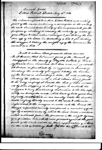
The Schedule referred to in these Letters Patent, and making part of the same, containing a description in the words of the said Samuel Jones himself of his improvements for the purpose of checking or retarding the velocity of road wagons stages & other wheel carriages & for taking the burden off of the horses in descending a hill & for checking the waggon & taking the weight off of the horses on the ascent of a hill.
To all to whom these presents shall come:
Be it known that I Samuel Jones of the Borough of Bridgeport in the County of Fayette & State of Pennsylvania have discovered that there was no good method known or practiced by waggoners or drivers of checking the velocity of wagons & taking the burden off the horses in descending a hill. The old method of locking the wheels with a lock chain being found to be very imperfect beside the loss of time occasioned by it in stopping to lock & again to unlock the waggon & being particularly destructive to the tire especially on turnpike roads which have of late years been so greatly multiplied in our country beside the insurmountable injury thereby caused to the roads & otherwise injurious to the waggon as well as to the horses. Although a partial remedy was found a number of years ago by a contrivance by which the hind horses were somewhat relieved from the pressure of the weight by means of a friction box which was pressed against the part front of the hind wheels by their application of a lever in the act of holding back. Yet this too is found to be
De avery
Page 3.
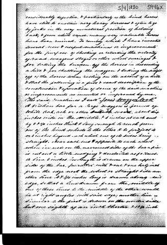
considerably defective, & particularly as the hind horses have still to sustain very heavy burdens & often to go by jerks in the very unnatural position of holding back, & from which cause many very valuable horses have been ruined. To remedy which I have invented several new & useful machines or improvements for the purpose of checking or retarding the velocity of road wagons stages or other wheel carriages & for taking the burden off the horses in descending a hill & for checking the wagon & taking the weight off of the horses when resting on the ascent of a hill & that the following is a full & exact description of the construction & operation of some of the said machines or improvements as invented or improved by me.
The said machines I call "Jones Wagon Lock" A friction bar for a large wagon is formed of white oak, ash or other suitable wood, about 4 inches wide in the middle, & 6 inches at each end by 2 & 3/4 inches thick & long enough to reach from one of the hind wheels to the other & to project 4 or 5 inches beyond each wheel one of its sides being straight. Near each end & opposite to each wheel when in use on the narrowest side of the bar a piece is cut out a little meddying & dovetailed as follows. A line 6 inches in length is drawn on the upper side of the bar, parallel with & one & one half inch from the edge next the wheel or straight side another line 4 & 3/4 inches long is drawn along said edge, so that a line drawn from the middle of one of these lines to the middle of the other would be at right angles with said edge; another line 2 similar to the first is drawn on the under side but one eighth of an inch shorter & 1/4 inch
Page 4.
from the lower edge; & another line corresponding with the second line is drawn along the edge at the under side also one eighth of an inch shorter, than the corresponding one on the upper edge, a line is then drawn from each end of each line on the same side of the bar, to the corresponding end of the other line. The pieces thus marked out is to be sawed & cut out to the mark; this is for a narrow wheeled wagon of two inch tire for a broader wheeled wagon the notch should be cut out proportionally wider; in the place where this piece is cut out a temporary wagging & dovetailing block is to be fitted which I call the friction block & which may be 3 or 4 inches in thickness; and should extend 4 or 6 inches above & below the bar; this temporary block may be knocked out & easily replaced when worn out; a notch made wagging & not dovetailing & a block made to fit it I believe would answer the purpose & perhaps equally as well as the other; another method of applying a temporary block is to bore 2 holes horizontally & crosswise thru each end of the friction bar, one on each side of the wheel, thru each of which, an iron clamp, or screw bolt about 3/4 of an inch in diameter & 8 or 9 inches long is to pass from the side next to the wheel, having a screw end on this end about 3 or 4 inches & a nut made to fit it, on the end of each of these, next to the wheel should be formed two strong wires the points of which should be about an inch & a half apart & so bent as to hold the block fast when it is placed between but of them, & which should be far enough apart for the wheel to turn around between, without touching them; any piece of wood or other substance suitable for sustaining the friction of wheels, placed between the clamps &
Page 5.
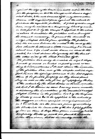
against the edge of the bar, or in a notch cut in the bar for the purpose; so that the clamps will have a sufficient hold; & the nuts screwed tight may serve when drawn with sufficient force against the wheels to produce the requisite friction. A plate of cast or wrought iron, may be nailed to a temporary block of wood or held fast to it by the clamps & applied to the wheels as above to sustain the friction when it might be deemed necessary. To prevent the dovetail or wedge shaped block from splitting the friction bar the corners between the notch & the end of the bar should be shaned a little rounding & a band about one & 3/4 inch wide drawn on close to the notch, & a nut drawn horizontally thru the bar at the other side of the block & riveted tight.
The friction bar may be varied in size & shape & made of wood or metal or part of each according to circumstances I do not claim the invention of the friction bar, nor of the staples which support it, nor the springs attached to it, but suppose them to be public property as they have been long in use on the old plan of applying the bar to the wheels by the hind horses as herein mentioned but I do claim as new & as my own invention or discovery the invention of the dovetail & wedge shaped notches in the friction bar & of the temporary blocks of wood & to be applied to the wheels of the wagon as above specified as my improvement on & substitute for the former plan of mortising the blocks into the lower side of the bar & fixing plates of iron on them to keep them from wearing, which temporary blocks of wood are found to answer better than iron, but as in many roads the
Page 6.
wood instead rather fast the above mentioned temporary blocks, might be plated with iron & in such case used to advantage. The friction bar when in use on a road-wagon or any other wagon or carriage to which it may be applicable, may be confined to & across the bottom of the bed, by two staples of sufficient strength & large enough to account the bar to play back & forward in them about 6 inches at the place where it comes in contact with the part of the hind wheels where the staples must be fastened to the longer bed rails for the purpose, by boring holes & inserting the prongs of the staples through & screwing a bar on each prong or a staple may be formed with straps running along its under side of the lower bed rail & fastened to it by two screw bolts with heads to each strap; passing thru the bed rail from above & thru the straps & fastened by burrs below. To keep the friction bar & blocks off from the wheels when not in use, in those methods of application herein described, where no other plan is described; I make use of two springs made of steel about 15 inches long & of sufficient strength to produce the desired effect, & long so that the bar may play 3 or 4 inches, one of these springs must be fastened to the hind part of each end of the bar so as to extend thru to the outside of the staple before mentioned. A shilled nail about half an inch thick should be driven into the underside of each end of the friction bar when in its proper place both either inside or outside of the staples as guides for the bar or otherwise two artificial wheels may be made of cast or wrought iron each about 3 1/4 inches in diameter.
Page 7.
6.
(or the diameter might be less if the prongs of the staples were bent so that their outer extremity should be perpendicular to the outer extremity of the lower box rail) 4 three-fourths of an inch thick, with a half inch hole thru the centre, 2 holes should be bored thru the friction bar, one at each side of the wagon bed, and side of under near to the staples as to admit the wheels to play against them for guides; 2 pins should be made about 4 inches long & half an inch square in thickness, with a head on one end, & a slit cut thru the other end to hold a key; one of these pins should be inserted thru each of the said holes in the bar, from above, thru the wheel which is to be fastened thereto by putting the key into the slit made to receive it.
To apply the friction bar to the purpose within mentioned I have invented a variety of methods, the following is a description of some of them; It is a follower. A shaft is made of iron for a common road wagon about one & a half inch square which is to be placed as near as practicable to the coupling pole where it should be a little lower & must lie parallel with & the centre of it to be about 3 inches from the front part of the hind bolster, & to extend from within 4 inches of the near side of the wagon bed, or that side where the driver usually walks to about 18 inches beyond the coupling pole where it should be rounded 2½ inches making a shoulder there, on this shaft at 10 inches each side of the middle of the coupling pole is fixed a roller 4 inches in diameter & 1½ inch thick, on the friction bar & back heart of each of which is permanently fixed a wooden staple
Page 8.
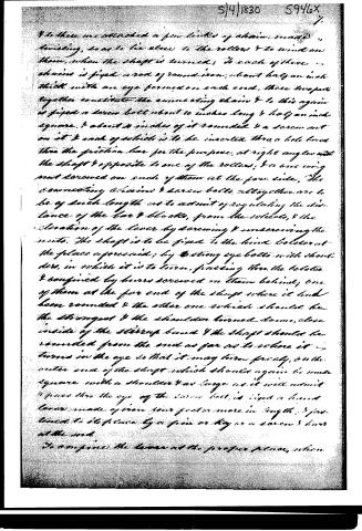
To these are attached a few links of chain, made, twisting, so as to lie close to the rollers & to wind on them, when the shaft is turned. To each of these chains is fixed a rod of round iron, about half an inch thick with an eye formed on each end. These two parts together constitute the connecting chains & to this again is fixed a screw bolt about 10 inches long & half an inch square, & about 4 inches of it rounded & a screw nut on it & each of which is to be inserted thro a hole bored thro the friction bar for the purpose, at right angles with the shaft & opposite to one of the rollers, & a one wing nut screwed on each of them at the fore side. The connecting chains & screw bolts altogether are to be of such length as to admit of regulating the distance of the bar & blocks, from the wheels, & the elevation of the lever by screwing & unscrewing the nuts. The shaft is to be fixed to the hind bolster at the place aforesaid, by 2 strong eye bolts with short- ders, in which it is to turn, passing thro the bolster & confined by burrs screwed on them behind; one of them at the far end of the shaft where it had been rounded & the other one which should be the strongest & the shoulder turned down, close inside of the string band & the shaft should be rounded from the end as far as to where it turns in the eye so that it may turn freely, on the other end of the shaft which should again be made square with a shoulder & as large as it will admit & pass thro the eye of the screw bolt, is fixed a hand lever made of iron four feet or more in length, & fastened to its place by a pin or key or a screw & burr at the end. To confine the lever at the proper place, when
Page 9.
8
the necessary friction is applied I have invented a number of ways, some of which I shall here describe, a cord or strap may be fastened to the end of the lever & brought forward & wound on a wheel, with a handle, that may be attached to the forward part of the wagon & stopped at the force required by a ray wheel & click, or a chain about 2½ or 3 feet long may be fastened to the lever about 1½ feet from the shaft on a foot from the other end, and a hook drove into the other end of the wrist piece, or to the lever best suit to latch it on when the requisite friction is attained.
When this machine is required to be applied, if the wheel is used, the operator takes hold of the bar & turns it until he has applied the requisite power, when the click on the ray wheel secures it until it is wanted to be withdrawn, he then raises the click & the springs force the bar off of the wheel, or if the chain is used to confine the lever, which mode I prefer, the operator takes hold of the hand lever & bears it down which rotates the chain on the rollers & draws the bar against the wheel, when he has applied the quantum of power which he judges necessary for the occasion, he confines the lever to its proper place, by hitching the lever chain to the hook, as aforesaid, & when the friction is to be withdrawn, he unhitches the chain & the springs pressing against the shanks of the staples, will throw the bar & blocks off of the wheel. I believe that a two or three shaft & gear might be substituted for the hand shaft roller & lever, by making them so strong as circumstances will admit & require; & strengthening
5/9/1830 59467
Page 10.
with iron bands, rivets & screw bolts, where necessary; & that wooden springs to the friction bar might be substituted for steel.
No. 2, is in every respect the same as No. 1, except that it has but one roller, connecting chains, screw bolts &c as described in No. 1, instead of 2 & which roller &c., should be placed directly over the coupling pole, where there is room for it, & consequently higher on the bolster, where there is not room, then as close to it as practicable, & must be applied in the same way, & the shaft may be shortened, to extend just beyond the coupling pole, where the eye for bolt, must be placed for it to turn in. No. 3, is the same machine as No. 1, & must be used in the same way; the only difference, is in the friction box which is to be cut off in 2 places in order to accommodate it to the wagons, the point of whose hounds rest on the coupling pole & therefore cannot conveniently be fixed to give room for it to play in its integral character; In the end of each piece, where it has been cut off & which must be previously banded with a strong iron band, must be fixed lengthwise a strong iron pin to project one inch or two & which must be inserted into a hole bored into the hounds for that purpose, & over which hole at each side, should be nailed a piece of iron, with a corresponding hole, to prevent the wood from wearing, & so placed that when a small block is fitted to the notch in each section of the bar & both blocks brought in contact with the wheels, each section will be in the range with the other, & as near horizontal as circumstances will admit, The connecting chains in this will again to be placed as
Page 11.
5/4/1830 5946X
11
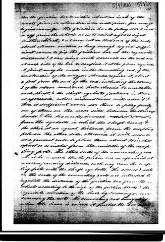
near the outer sides of the wagon bed as practicable. S.4. As a substitute for the roller connecting chains & screw bolt, described in S.14 for the purpose of pushing back the friction bar & blocks from the wheels when not in use; instead of using the patentized springs, on the friction bar, for that purpose, which are liable to get out of order, as well as to simplify the mechanism & save expense, I have invented the following described eyebolt, which I shall call the shaft eye bolt, & connecting rod or chain. Thus, the shaft, where the roller in S.1 is to be described to be placed & which at that place should be made a little the strongest, a hole must be punched about one inch square, at the forward side, & tapering to about half an inch, at the opposite side; the shaft eye bolt should be made with a shank, just to fit the said holes & project there, the shaft, about 3/4 from the span inch, which projection should be rounded & a screw cut on it & a burr fitted to & screwed tight on it. At the forward side of the shaft, the eye bolt should be 2 3/4 inches long, 1/2 inch perpendicular width & 3/4 of an inch thick; which consequently forms a shank & which shoulder should be placed on the upper side. The forward corners should be rounded & a hole full half an inch or more diameter punched there, horizontally at such distance as that the centre of the hole should be 2 1/2 inches from the centre of the shaft; thus this hole or eye must be inserted one end of a half inch rod of round iron & an eye turned & screwed on it, & which with the eye of the shaft eye, is to form a joint, which should work close but freely with the inner end of the lever. The other end of this connecting rod, should extend forward
Page 12.
5/4/1830 5946X
then the friction bar to within about an inch of the waste piece, or where there is no waste piece, far enough to give room for the friction bar to play 4 or 5 inches off from the wheels, so as to admit a good sized friction block; & a screw cut on that end of the rod, about eleven inches or long enough to give sufficient room to fit the friction bar at the requisite distance; 2 one wing nuts screwed on the rod, one at each side of the bar to confine it at the place required. A joint may be made in the connecting rod, if the construction of the wagon should require it, about a foot from the end of the rod, including the screw; 2 of the above mentioned holes should be made in each shaft, & the shaft eyebolts fastened in them as aforesaid, when circumstances will admit; & there is sufficient room for them to play freely, one of them on the near side, between the steering hands & the hands, inward, from the eyebolts, in which the shaft turns; & the other at an equal distance from the coupling pole on the other side, otherwise it will answer as a general rule, to place them about 20 inches apart or 10 inches from the middle of the coupling pole. The other ends of the connecting rod must be inserted thru the friction bar as aforesaid at a corresponding distance, each way from the coupling pole with the shaft eyebolts. The screws & nuts on the ends of the connecting rods are intended to regulate the distance of the friction bar from the wheels according to the size of the friction blocks & the requisite elevation of the lever by screwing or unscrewing the nuts. The connecting rod being stiff when the lever is raised it pushes the bar out.
Page 13.
12
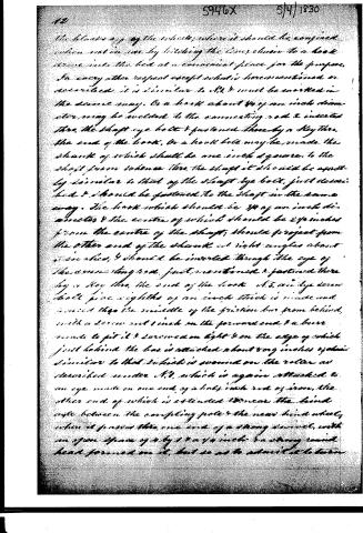
the block off of the wheel, where it should be confined when not in use, by hitching the lower chain to a hook drawn into the bed at a convenient place for the purpose. In every other respect except what is here mentioned or described, it is similar to No. 1 and must be worked in the same way. A hook about 3/4 of an inch diameter may be welded to the connecting rod & inserted thru the shaft eye bolt & fastened thereby a key thru the end of the hook. Or a hook bolt may be made the shank of which shall be one inch square, to the shaft from whence thru the shaft it should be apertly similar to that of the shaft eye bolt, just described & should be fastened to the shaft in the same way. The hook which should be 3/4 of an inch diameter & the centre of which should be 2 1/2 inches from the centre of the shaft, should project from the other end of the shaft at right angles about 6 inches, & should be inserted through the eye of the connecting rod, just mentioned & fastened thereby a key thru the end of the hook. A 5/8 inch eye screw bolt five eighths of an inch thick is made and screwed thru the middle of the friction bar from behind, with a screw cut 1 inch on the forward end & a burr made to fit it & screwed on tight & on the edge of which just behind the bar is attached about 8 or 9 inches again similar to that which is screwed on the roller as described under No. 1, which is again attached to an eye made on one end of a half inch rod of iron, the other end of which is extended 10 inches the hind angle between the coupling pole & the near hind wheel, when it passes thru one end of a strong screw, with an open space of 4 by 1 & a 1/4 inch & a strong round head formed on it, but so as to admit it to turn
Page 14.
5/9/1830 S946X 13
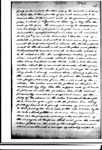
precisely in the middle; the other end of the screw is to have a hole thru it three fourths of one inch diameter & to receive thru it the small end of the following screw pin, & which is to be fastened there by a key thru the end of the pin. The screw pin may be made from one & a half to 2 1/2 feet in length, & one inch in diameter except about 5 inches of it, which is to be 3/4" of an inch diameter & thru the end of which a place is furnished to receive a key, a screw must be cut, about 1/2 inch in the thickest part, next to the small end and the other end flattened & shouldered to receive a crank or handle which is to be fixed to it. An antiplication roller of cast iron must be made about 2 1/2 inches diameter, & one & a half inch thick, with a hole thru the centre, about 3/4 of an inch diameter. A strong cup of iron must be made to fit on, & across the coupling hole, & firmly nailed there, having a pin on the near end, of a size to fit in the roller, & rise perpendicular from the near end of the strap. The roller must be fitted on the pin & confined by key. Thru the upper end of it must be placed as near the friction bar, at its nearest proximity as will give sufficient room for the play of the chain on the roller & conduct the draught in a line at right angles with the friction bar. A strong plate of iron is to be firmly attached by screws or nails to that part of the kind rope, or the rope & belter together, or to a block fitted in between them & fastened there for the purpose, according to the construction of the swing, at the place that will give the crank, when fitted on the end of the shaft or screw pin above mentioned a sweep of about 7 inches & ...
Page 15.
reason for the hand to turn it, without touching the coupling pole, or any other part of the waygon; then this plate must be a female screw one inch in diameter; in a direction toward the far side of the roller, & where wood intervenes, a hole must be bored thru it in the same direction & at the forward side, must also be a plate of iron with a hole thru it 3/4 of an inch in diameter in the same direction & firmly fastened there, as a guide, & support to the screw pin; To put it together the screw pin is screwed thru the screw plate, the small screw fast thru the other plate & thru one end of the screw before mentioned & fastened there with a key, and when going to use it the operator takes hold of the crank & turns it so as to withdraw the screw, which draws the friction bar with the blocks against the wheels & causes the necessary friction, & to remove them from the wheels the motion is reversed; when the springs on the bar will push them off—
No. 6. A shaft of iron is formed, one inch square & about 30 inches long, more or less according to the width of the waygon bed; & placed under & across the bed at right angles, just behind and at such distance from the friction bar as will be most convenient; to connect the machine there with & give it full scope for operation & reaches from within about 5½ inches of the near side of the bed to about 1 inch beyond the coupling pole, where the end of it is rounded & placed in a strong eye bolt, the shank of which passes thru the pole & is fastened by a bolt screwed in the end below & also a screw cut on that end of the shaft & a bar screwed on it, to confine it
Page 16.
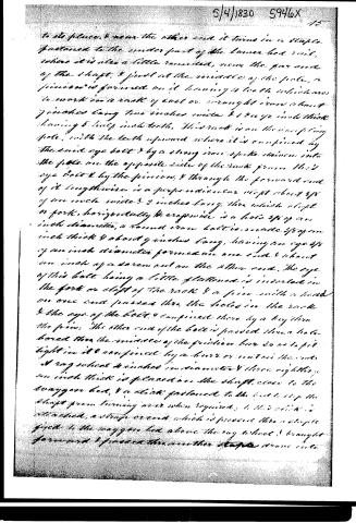
to its place, & near the other end it turns in a staple fastened to the under part of the lower bed rail, where it is also a little rounded, near the far end of the shaft. I find at the middle of the pole, a pinion is formed on it having a tooth which is to work in a rack of cast or wrought iron about 7 inches long two inches wide & 1 1/4 inch thick having 5 half inch teeth. This rack is on the rising pole, with the teeth upward where it is confined by the said eye bolt & by a strong iron spike driven into the pole on the opposite side of the rack from this eye bolt & by the pinion, & through the forward end of it lengthwise is a perpendicular slot about 3/8 of an inch wide & 2 inches long, thru which slot a fork, horizontally & crosswise is a hole 3/8 of an inch diameter, a round iron bolt is made 3/8 of an inch thick & about 9 inches long, having an eye 3/8 of an inch diameter formed on one end & about an inch of a screw cut on the other end. The eye of this bolt being a little flattened is inserted in the fork or slot of the rack & a pin with a head on one end passed thru the holes in the rack & the eye of the bolt & confined there by a key thru the pin. The other end of the bolt is passed thru a hole bored thru the middle of the pinion box so as to fit tight in it & confined by a burr or nut in the ends & a rag wheel 4 inches in diameter & three eighths of an inch thick is placed on the shaft, close to the waggon bed, & a stick fastened to the bed to stop the shaft from turning over when required. To this stick is attached, a strap or cord which is passed thru a staple fixed to the waggon bed above the rag wheel & brought forward & passed thru another staple above into
Page 17.
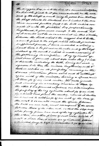
the spongon box, or into the bed at a convenient place, a handle fixed to it for convenience, on the near end of the shaft a crank may be fitted & in that case the shaft should be shortened 2 or 3 inches & the machine moved further back & the bolt which connects it with the friction box proportionally lengthened, to give more sweep to the crank, but as it would not be so convenient in this situation, between the hind wheel & the spongon bed to turn a crank fixed to the shaft, which should produce sufficient power, I have invented a sliding hand lever to be placed on the outer end of the shaft instead of the crank & which is made according to the following description. A ray cylinder of cast iron is formed about 4/4ths inches long & 2 inches in diameter including the teeth, having an inch square hole thru the middle, lengthwise, with 6 teeth or catches on its periphery running in the same direction from each end to within 1/4 of an inch of the middle, leaving a space round it there 1/4 of an inch wide. The teeth of each end standing in a contrary direction to those of the other & are formed as follows, one side rises from the periphery of the ray cylinder about 1/4 of an inch in a direct line from the centre, whence it declines in a curve to within 1/4 of an inch of the base of the next & so on a circle round the space between the teeth on one end, must correspond with the space between those of the other end, so that the step may slide freely from one end of the ray cylinder to the other, an other piece of cast iron which I call a lever box, is made of a cylindrical form 2 1/2 inches long & 1 1/2 in diameter & 1/4 of an inch
Page 18.
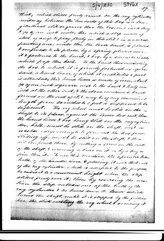
thick, which slides freely round on the rag cylinder midway between the two ends of this box is a longitudinal slit or groove thru the box, one inch long & 1/4 of an inch wide, thru which a stop made of steel of a size to play freely in this slit & in a corresponding one, made thru the lower band, is placed & confined to its place, by a spring placed over it & fastened to the band, & box, by a screw or rivets, which pass thru both. To the band thus encircling the box, to which it is firmly fastened as afore said, a hand lever, of which it constitutes a part is attached; this hand lever is made of iron, about 3/4 of an inch square, next to the band & only one inch at the other end; & the above mentioned band formed on the end of it, & may be of any convenient length from 20 inches to 2 feet is supposed to be sufficient. The rag wheel must be slid on the shaft, to its place, against the lower bed rail, then the hand lever & box being slid on the rag cylinder, both must be slid on the shaft, next a washer large enough to prevent the box from sliding off, must be slid on the shaft, & then it's confined there, by cutting a screw on the end of the shaft, & screwing a turn on it or by a key or pin thru it. To use this machine, the operator takes hold of the hand lever, & placing it over that end of the rag cylinder which is adapted to the purpose, he raises it to a convenient height when the stop slides freely over it; then by reversing the motion the stop catches one of the teeth of the rag cylinder & he lowers down the lever which turns the shaft, until it is stopped by the friction bar, the stick catching the rag wheel & screwing it
Page 19.
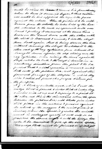
until he raises the lever & removes his purchase, when he bears it down as before, & thus continues until he has applied the requisite force against the wheels. When the friction is to be withdrawn from the wheels, he takes hold of the handle attached to the cord as aperiod with one hand & pulling it downward at the same time bears on the hand lever with the other until the slide is loosened & raised, & lets the shaft turn back again. And to bring down the lever without turning the shaft, he slides it to the other end of the ray cylinder from whence it is brought down again, the stop sliding over the ray cylinder, when raising the lever again the stop catches the tooth, & the shaft is turned in a contrary direction from the first & the bar pushed back & which operation is renewed until both ends of the friction bar rest against the forward prongs of the stopper in which they slide & which are placed at a proper distance for the purpose.
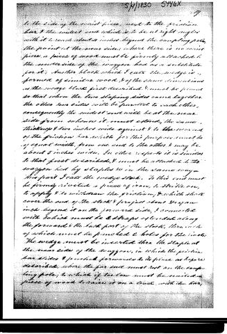
87. A block of suitable wood, which I call the wedge block is formed 2 inches thick 12 inches long, 4 inches wide at one end & tapering to a point at the other end. This is the dimensions when the space between the friction bar; with blocks five inches thick fitted in the notches & pressed against the wheels of the wagon & the waist piece is 4 inches; when the space is greater the width must be enlarged equally at each end so as to preserve the same angle & with the wedge hereafter to be described to fill up the said space, this wedge block must be formed or of that pat
Page 20.
to the side of the waist piece, next to the friction bar & the waist end which is to be at right angles with it to reach about 2 inches beyond the sampling pole, the point at the near side; where there is no waist piece, a piece of wood must be firmly attached to the underside of the waggons bed as a substitute for it; Another block which I call the wedge is, formed of similar wood, & of the same dimensions as the wedge block first described & must be placed so that when the two sloping sides come together the other two sides will be parallel to each other, consequently the waist end will be at the near side from whence it must extend, the same, thickness & two inches wide against & to the near end of the friction bar which for this purpose must be of equal width, from one end to the other, & may be about 5 inches wide. In other respects it is similar to that first described, & must be attached to the waggons bed by staples so in the same way—this part I call the wedge stock. To this end must be firmly riveted a piece of iron, to strike on, to apply & to withdraw the friction, & which shall cover the end of the stock & project about 1/4 an inch beyond it on the forward side, & connected with which must be 2 straps of iron along the forward & the back part of the stock, then each of which must be punched 2 holes for the rivets. The wedge must be inserted thru the staple at the near side of the waggons, in which the friction bar slides & pushed forwards to its place as before described, where the far end must rest on the sampling pole, to which if too low must be nailed a piece of wood to raise it on a level with the bar.
Page 21.
29
The rear and resting on the staple: A stubbed nail must be driven into the under side of the wedge stock inside of the staple to keep it from slipping out. A hammer of cast or wrought iron, of a suitable weight & form with a handle of convenient length, must be prepared & may be fixed by a cord or chain, to the friction bar or the wagon bed or waist-piece, with which the operator strikes on the end of the wedge stock to cause the friction against the wheels & to withdraw it, he strikes in a contrary direction against the above mentioned projection.
What I claim as new & as my own invention or discovery in the above described machine, & for which I ask an exclusive privilege, is as well the improvement of the dovetail & wedge shaped notches in the friction bar & of the temporary blocks of wood &c. to be applied to the wheels of road wagons, stages &c. as herein specified & the machines or methods of applying the friction bar, with the blocks as herein described & before claimed to be my invention, under the heads of U.S. 2d. & 4th. all involving the same principle of the hand lever, U.S. 1st. involving the principle of the screw & crank, No. 6. involving beside the hand lever & the crank, the friction & rack, & No. 7. involving the principle of the wedge, as the main general principle which is involved in all of them, of the manual application & maintenance at pleasure, of a sufficient & regular & determinate friction against the wheels of the wagons or carriages & the means of the mechanical power
5/4/1830 5946X
Page 22.
and which may be performed with ease & expedition without stopping the horses to apply at
Witnesses
James Simmon
Idem V. Ball
Sam Jones
(Received & Recorded anew April 12, 1844)
7260 words
much obdurate
Drawing
5/4/1830 5946X 21
Published accounts: journal notice
Notice in the monthly list of patents, with remarks
Journal of the Franklin Institute, new ser., vol. 6 (1830), p. 73 · View the page
1. For Sundry Machines for the purpose of Checking, or Retarding, the velocity of Road Wagons, stages, and other wheeled carriages, denominated "Jones' Wagon Lock;" Samuel Jones, Bridgeport, Fayette county, Pennsylvania, May 4.
Remarks. An elaborate description of eleven pages introduces us to an acquaintance with this invention, or rather these inventions, which consist of different modes of accomplishing the same object. A friction bar is to be made to press against the front part of the hind wheels of the wagon or carriage; this friction bar is to exceed in length the distance between the wheels; such a bar it is particularly stated, has been long in use, but the present patentee claims as new the application of friction blocks upon the friction bar. A dovetailed notch is to be cut into the bar, opposite to each wheel, and blocks of wood are fitted into these notches; the blocks being wedge shaped, are readily knocked out and replaced, as they wear away. It is proposed to face some of these blocks with iron. Divers modes are proposed of causing the friction blocks to bear against the wheels, as will be perceived by the subjoined claim, which must complete our account of this invention. "What I claim as new, and as my own invention, or discovery, in the above described machines, and for which I ask an exclusive privilege, is as well the improvement of the dovetailed and wedge VOL. VI. No. 2. - AUGUST, 1830. 10 shaped notches in the friction bar, and of the temporary blocks of wood, &c. to be applied to the wheels of road wagons, stages, &c. as herein specified, and the machines, or methods of applying the friction bar with the blocks, as herein described, and before claimed to be my invention, under the heads of No. 1, 2, 3 and 4; all involving the same principle of the hand lever; No. 5, involving the principle of the screw and crank; No. 6, involving beside the hand lever, and the crank, the pinion and rack; and No. 7, involving the principle of the wedge; as also the main general principle which is involved in all of them, of the manual application, and maintainance at pleasure, of a sufficient, regular and determinate friction, against the wheels of the wagon, carriage, &c. through the means of the mechanical powers: and which may be performed with ease and expedition, without stopping the horses to apply it."
About this record
- Patentee
- DATAMP
- Date
- the Name and Date index of patents, DATAMP, USPTO records
- Invention
- DATAMP
- Listed in
- the Name and Date index of patents, DATAMP, USPTO records, Jim Shaw's X-patent list, the Journal of the Franklin Institute, Burke's List of Patents (1847)
- Burke's 1847 Patent Office list gives the same patent.