

Drawings and documents
USPTO scan
The patent as scanned by the USPTO
-
 Page 1
-
 Page 2
-
 Page 3
-
 Page 4


U.S. Patent and Trademark Office · Google Patents
Show the transcription Hide (1,119 words)
Machine transcription (LightOnOCR) of the pages as scanned by the USPTO, most of them the handwritten copies made when the records were restored after the 1836 fire. Not checked; it can misread handwriting, so compare it with the scan.
Page 2.
United States Patent
Patent No.: X5948
Josiah A. Clarke
Letters Patent
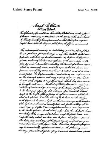
The Schedule referred to in these Letters Patent and making part of the same containing a description in the words of the said Josiah A. Clarke himself of his improvement in that part of an improved Carpet Loom called the Engine which forms the figures or ornaments.
This improvement consists in substituting a rotary sheet of Paste Board, parchment, painted Canvas, or any other suitable substance perforated with holes in such a manner as to form the figures required, in lieu of the barrel or cylinder with wire cogs or staples set in it (somewhat resembling the barrel of a hand organ) which is commonly used, and also as a substitute for an improvement on the lay card machine, so called, or as it is sometimes called, “the paper machine” and also as an improvement on the Canvas apron with cogs or strips of wood attached to it and with staples set in these cogs, which has been recently brought into use. The sheet of Paste Board, etc., required will be of various size according to the design of the figure to be laid out upon it, but always of a breadth about equal to the length of the cylinder or cylinder around which the sheet is to operate. And on this sheet is to be laid out the design for the figures to be woven by it in the same manner as the surface of the cylinder or barrel is usually laid out for the setting of the wire cogs, or staples, and in every place where a wire cog would be set in the cylinder, punch or eat a fair hole thro’ the paste board, and all these holes in equi distant lines across the paste board, and beside the holes, which are laid out to form the figures, punch other holes near each edge of the paste board in about every second or third line of the figure holes. This sheet being thus prepared may be conveniently applied and used in the following manner (viz.) please a suitable cylinder of any convenient diameter and of such
Page 3.
United States Patent
Patent No.: X5948
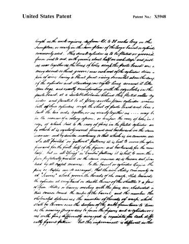
length as the work requires, say from 21 to 38 inches long in the same place, or nearly in the same place of the large barrel or cylinder commonly used. This small cylinder is to be fluted or grooved from end to end, with grooves about half an inch deep and just as near together as the lines of holes across the paste board are. In every second or third groove, near each end of the cylinder, drive a pin of wire having a blunt point rising somewhat above the surface of the cylinder and standing in right lines around it like spur cogs, and exactly corresponding with the edge holes in the paste board, at a suitable distance behind this fluted roller cylinder and parallel to it, place another plain cylinder around both of these cylinders, wrap the sheet of paste board and lace it back the two ends together, or as nearly together as may be in the manner of a rotary apron, or creper. The rows of holes in the edges of which suit to the rows of pins in the fluted cylinder and by which it is regularly moved forward and backward in the same manner, and by similar machinery to that which is in common use in all "pointed" or "gathered" patterns it is best to move the apron forward for the first half of the figure, and backward for the second half, but in all "spring" or "bumbel" patterns it is best to move the apron perpetually forward in the same manner as is known and practiced by all carpet weavers. In the barrel or cylinder engage the pins or staples, are so arranged, that the wire slides commonly called "Leavers" which govern the threads of the warp, slide towards the cylinder at every "hand" or double throw of the shuttle & a pair of these slides or leavers meeting with the pins, are obstructed in their course toward the centre of the barrel and the number thus obstructed determines the number of threads of warp, which shall be thrown over the surface of the web from time to time as the weaving progresses to form the figures and a cylinder or reel with pins differently arranged is requisite for each differently figured pattern. But this improvement is different in that
Page 4.
United States Patent
Patent No.: X5948
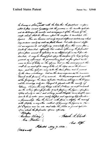
which the leaves or slides, made with the holes thro' the pasteboard are permitted to pass inward by entering into the grooves in the smaller cylinder and so determine the number and arrangement of the threads of the warp which shall be thrown upon the surface to constitute the figures. There are however not only several different substances which may answer nearly as well as paste board, but also several different arrangements not differing essentially from that more particularly described, especially that instead of having the perforated apron pass around 2 cylinders in an elliptical form as before described, it may be bound fast upon the surface of a large cylinder grooved as aforesaid, the grooves being just as far apart as the rows or lines of holes in the apron. But in this arrangement there will be no need of so many holes at the edges as in the former case, and this cylinder may take the same place and be moved by the same machinery, and in the same manner as the common barrel with pins in it is moved. In this arrangement as well as the foregoing, the same cylinder continues always on the Engine and the coverings only are changed to operate all the variety of patterns. I confine the only things which I claim as improvements are the rotary apron perforated, so as to perform the figures (upon principles already in use) and as being much cheaper, more simple, more sure to be in order, more easily shifted and requiring less attention in foremanship than the barrel with pins or staples, the canvas with staples or any other method of forming the figures in carpet Engines now in use and also the fluted or grooved cylinders upon which the perforated apron operates.
Witnesses
Ambrose Whiting
Asa Barber
Joshua R. Clark
Exd. Mgr.
Patented May 7, 1830.
(1144 words)
Published accounts: journal notice
Notice in the monthly list of patents, with remarks
Journal of the Franklin Institute, new ser., vol. 6 (1830), p. 74 · View the page
3. For an improvement in that part of the Ingrain Carpet Loom, which is called the engine; Josiah R. Clark, South Coventry, Tolland county, Connecticut, May 7.
Remarks. (See the specification.)
Published accounts: journal notice
Notice in the monthly list of patents, with remarks
Journal of the Franklin Institute, new ser., vol. 6 (1830), p. 88 · View the page
This completes the construction of the evaporating basin; water is now to be poured in the open end of the lower basin, which is beyond the board aforesaid, until it fills up all the space that is between the two basins. Fire is then put to the furnace until the water boils, and then the foot water or the liquor remaining after boiling the oil from the bones and feet, is to be run into the upper basin, and the fire kept up until the foot water is evaporated to a proper consistence to be taken out and put into cooling troughs, where it afterwards is cut and spread on nets to dry. This completes the process. The improvement for which your petitioner claims an exclusive right, is the construction of the double floored evaporating basin, and the application of it to the purposes of making glue, described as aforesaid, whereby the foot water, or liquor after boiling the bones of all kinds of animals, is evaporated into a proper consistence to preserve it, and make it into glue. PETER COOPER. Specification of a patent for an improvement in that part of the Ingrain Carpet Loom, which is called the Engine. Granted to JoSIAH R. CLARK, South Coventry, Tolland county, Connecticut, May 7th, 1830.
Remarks. THIS improvement consists in substituting a rotary sheet of pasteboard, parchment, painted canvass, or any other suitable substance, perforated with holes in such a manner as to form the figure required, in lieu of the barrel or cylinder with wire cogs, or staples, set in it, (somewhat resembling the barrel of a hand organ) which is commonly used; and also as a substitute for, and an improvement on " the Jay Card Machine," so called, or as it is sometimes called, "the Paper Machine;" and also as an improvement on the canvass apron with cogs or strips of wood attached to it, and with staples set in these cogs, which has been recently brought into use. The sheet of pasteboard, &c. required, will be of various size, according to the design of the figure to be laid out upon it, but always of a breadth about equal to the length of the cylinders, or cylinder, around which the sheet is to operate, and on this sheet is to be laid out the design for the figures to be woven by it in the same manner as the surface of the cylinder, or barrel, is usually laid out for the setting of the wire cogs, or staples; and in every place where a wire cog would be set in the cylinder, punch, or cut, a fair hole through the pasteboard; and all these holes in equi-distant lines across the pasteboard; and besides the holes which are laid out to form the figure, punch other holes near each edge of the pasteboard in about every second or third line of the figure holes. This sheet, being thus prepared, may be conveniently applied and used in the following manner, viz. place a small cylinder of any convenient diameter, and of such length as the work requires, say from twenty-one to thirty-eight inches long, in the same place, or nearly in the same place of the large barrel, or cylinder, commonly used; this small cylinder is to be fluted, or grooved, from end to end, with grooves about half an inch deep, and just as near together as the lines of holes across the pasteboard are; in every second or third groove, near each end of the cylinder, drive a pin of wire having a blunt point rising somewhat above the surface of the cylinder, and standing in right lines around it, like spur cogs, and exactly corresponding with the edge holes in the pasteboard. At a suitable distance behind this fluted cylinder, and parallel to it, place another plain cylinder; around both these cylinders wrap the sheet of pasteboard, and lace, or tack, the two ends together, or as nearly together as may be, in the manner of a rotary apron, or creeper, the rows of holes in the edges of which suit to the rows of pins in the fluted cylinder, and by which it is regularly moved forward and backward, in the same manner, and by similar machinery, to that which is in common use. In all " pointed," or "gathered" patterns, it is best to move the apron forward for the first half of the figure, and backwards for the reverse half; but in all "sprig," or "cumber" patterns, it is best to move the apron perpetually forward, in the same manner as is known and practised by all carpet weavers. In the barrel, or cylinder, engine, the pins or staples are so arranged, that the wire slides, commonly called "levers," which govern the threads of the warp, slide towards the cylinder at every "hard," or double throw of the shuttle, and a part of these slides, or levers, meeting with the pins, are obstructed in their course towards the centre of the barrel, and the number thus obstructed determines the number of threads of warp which shall be thrown over the surface of the web, from time to time, as the weaving progresses, to form the figures; and a cylinder, or barrel, with pins differently arranged, is requisite for each differently figured pattern. But this improvement is different, in that the levers, or slides, which meet with the holes through the foster-board, are permitted to pass inward by entering into the grooves in the smaller cylinder, and so determine the number and arrangement of the threads of the warp which shall be thrown upon the surface to constitute the figures. There are, however, not only several different substances which may answer nearly as well as pasteboard, but also several different arrangements not differing essentially from that more particularly described; especially, that instead of having the perforated apron pass round two cylinders in an elliptical form, as before described, VOL. VI. No. 2. -AUGUST, 1830. 12 : 1 1 it may be bound fast upon the surface of a large cylinder, grooved as aforesaid; the grooves being just as far apart as the rows or lines of holes in the apron; but in this arrangement there will be no need of so many holes at the edges as in the former case; and this cylinder may take the same place and be moved by the same machinery, and in the same manner, as the common barrel with pins in it is moved. In this arrangement, as well as the foregoing, the same cylinder continues always on the engine, and the coverings only are changed to operate all the variety of patterns.
Published accounts: journal notice
Notice in the monthly list of patents, with remarks
Journal of the Franklin Institute, new ser., vol. 6 (1830), p. 90 · View the page
In fine, the only things which I claim as improvements are the rotary apron perforated so as to form the figure (upon principles already in use) as being much cheaper, more simple, more sure to be in order, more easily shifted, and requiring less attention in foremanship, than the barrel with pins, or staples, the canvass with staples, or any other method of forming the figures in carpet engines now in use; and also the fluted, or grooved cylinder, upon which the perforated apron operates. JOSIAH R. CLARK. Specification of a patent for an improvement in the mode of preparing Paddy, or Rough Rice, suitable for culinary purposes. Granted to JOHN L. NORTON, of the City of New York, at present residing in Charleston, South Carolina, May 7th, 1830.
Remarks. THE paddy, or rough rice, after having been sifted through a screen of wire cloth to separate it from the defective light rice and dust, or sand, descends, or is conveyed to a pair of mill stones, for the purpose of shelling, or removing the external hull, or shell; from the stone the rice passes a wind fan, to separate the chaff, or outer husk, from the shelled rice, which is next to be conveyed to a screen of wire cloth, of two degrees of fineness, the finest part being at the most elevated end, is adapted to let out the dust, or sand, and the lower, or coarser part, to allow the shelled rice to pass through; and such grains as may have escaped from the stones without being shelled, will not pass through this wire cloth, but be delivered at its lower end to be passed again to the stones. The process so far described, has been known and used for a long period of time, and I distinctly disclaim all exclusive privilege to the use of any part, or parts, of the foregoing process. But rice has also an internal pellicle, or skin, which, although very thin, requires to be removed before it is fit for culinary use, and which is not effected by the previous operation of the stones or screens. The following is a full and exact description of my improvement.
DATAMP: illustration
Illustrations from DATAMP
DATAMP (Directory of American Tool and Machinery Patents), via the Internet Archive · Archived DATAMP page
About this record
- Patentee
- DATAMP
- Date
- the Name and Date index of patents, DATAMP, USPTO records
- Invention
- DATAMP
- Listed in
- the Name and Date index of patents, DATAMP, USPTO records, Jim Shaw's X-patent list, the Journal of the Franklin Institute, Burke's List of Patents (1847)
- Burke's 1847 Patent Office list gives the same patent.