

Drawings and documents
National Archives restored drawings: drawing
J. Willard's Patent Drawing for a Bridle Birch Press

National Archives, Restored Patent Drawings (Record Group 241) · Full-size scan at the National Archives · Catalog record
Show the text on the drawing Hide (33 words)
Words on the drawing as machine-read by the National Archives; not checked. Useful mainly for searching.
fir / J.WILLARD'S / Bridle Brick Press, / 60 2%x / DIV LE ION. / Patented June 10th 1850. / I'O / cr
National Archives restored drawings: drawing
John Estlin's Patent Drawing for a Furnace for Burning Stone Coal or Charcoal

National Archives, Restored Patent Drawings (Record Group 241) · Full-size scan at the National Archives · Catalog record
Show the text on the drawing Hide (66 words)
Words on the drawing as machine-read by the National Archives; not checked. Useful mainly for searching.
$350 / 6027 1/2 / John Estlin, / Furnace for Burning Stone Coal or Charcoal. / Patented June 19th 1830. / Fr / I.I. / 35 / Drawing made from Original Patent, / LOANED BY / J.L. Estlin, D.D., Son of John Estlin, Inventor; / To replace the Original Drawing destroyed in the Fire of 1836. / October 14th 1903. / C.M.Jrelan Chief Clerk. / as.
USPTO scan
The patent as scanned by the USPTO
-
 Page 1
-
 Page 2
-
 Page 3
-
 Page 4


U.S. Patent and Trademark Office · Google Patents
Show the transcription Hide (1,231 words)
Machine transcription (LightOnOCR) of the pages as scanned by the USPTO, most of them the handwritten copies made when the records were restored after the 1836 fire. Not checked; it can misread handwriting, so compare it with the scan.
Page 1.
6027X
J. Willard,
Brick Machine,
Patented June 10, 1830.

AM. PHOTO-LITHO. CO. N.Y. (OSBORNE'S PROCESS)
Page 2.
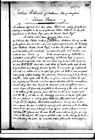
Julius Willard, of Baltimore, State of Maryland.
Letters Patent.
The schedule referred to in these Letters Patent and making part of the same containing a description in the words of the said Julius Willard, himself of his Improvement in the Brick Press under the "Bridle Brick Press."
To all to whom these presents shall come,
Be it known that I Julius Willard of Baltimore, Baltimore County and State of Maryland, have invented a new and useful improvement in the Brick press called "Willard's Bridle Brick Press," and that the following is a full and exact description of the construction and operation of the said machine as invented by me, to wit:
In the annexed drawing A,B,C,D, is a substantial wooden frame about 4 feet long, 2 1/2 inches high, and from one foot to one foot 2 1/2 inches wide, the cross posts may be six inches square and the rails E,F,G,H, about three inches thick, by twelve inches deep, the whole being mortised and strongly joined together and connected by cross pieces. Two semicircles are notched out in the upper edges of the rails G,H, to receive and permit to move freely without touching the cylindrical transverse arms, (C,C,) of the main lever (L), which together with the lever are of iron, and cast solid; the arms C,C, projecting over the rails and have square shoulders with two round pinions Z; also along their sides towards the short arm of the lever (L) is cast a square tongue (T) (scarcely perceptible in the drawing) the outer ends rest in the bottom of two grooves faced with iron on the inner surfaces of the rails G,H, (not seen in the drawing) and serve at one part of the operation as a fulcrum or resting point to the lever (L) which will be explained hereafter (T.) is the piston rod which is cast iron having near its lower end a square shoulder, in which the extremity of the short arm of the lever L to be held on it, its foot descends through a large square mortise (R,) in a wooden cross piece (N) framed into the rails G,H, and is acted on by five grooving screws, in the cross piece N, only one of which is seen in the drawing for the purpose of levelling the piston on movable bottom plate of the mould, which is
G. W. for L.
Page 3.
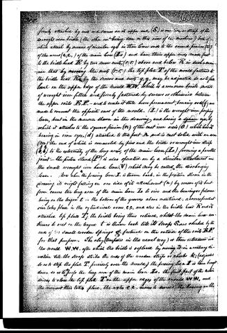
firmly attached by nuts and screws on its upper end, (S) is one side or strap of the wrought iron bridle (the other not being seen in this view of the machine) both of which attach by means of circular eyes in their lower ends to the second pinion (P) of the arms (e, e,) of the main lever (Ia) and have their upper ends made fast to the bridle head R by two screw nuts, (r, r,) above and below R in such a manner that by moving the nuts (r, r,) the top plate T of the mould fastened to the bridle head R by the screws and nuts g, g, may be adjusted so as to be level on the upper edge of the mould W, W, which is a common bridle plate of wrought iron fitted and firmly fastened by screws or otherwise between the upper rails F, F, - and to make it little more permanent, bracing rods (f) are made to connect the opposite ears of the mould. (I,) is the wrought iron pressing lever, but in the manner shown in the drawing and having a square eye, by which it attaches to the square pinion (N) of the cast iron axis (O,) which has its bearing in iron eyes, (d,) attached to the foot A and is cast solid with an arm (m,) the end of which is connected by pins and the bridle or wrought iron strap (t, t,) to the extremity of the long arms of the main lever (Ia) forming a parallel joint - the piston stand (P) is also operated on by a similar attachment and the small wrought iron hand lever (V) which may be called the discharging lever. Now when the pressing lever I, is thrown back, in the position shown in the drawing, its weight falling on one side of its attachment (n,) by reason of its bent form, causes the long arm of the main lever Ia to rise and the bearings or fulcrums being on the tongues t in the bottom of the grooves above mentioned, a corresponding rise takes place in the cylindrical arms e, e, and also in the bridle head R and its attached top plate T, the bridle being thus relieved, whilst the main lever continues to rest on the tongue t is thrown back till its straps S are checked by the ends of two small wooden springs S, fastened on the outside of the rails B, B, for that purpose. The clay (tempered in the usual way) is then introduced into the mould W, W, after which the bridle is replaced by moving it in a contrary direction till the straps strike the ends of the wooden strips or checks K, (adjusted so as to stop the plate T, precisely over the mould,) the pressing lever I is then brought down so as to press the long arm of the main lever Ia, the first part of the motion serves to close the top plate T on the upper edges of the moulds W, W, and the moment this takes place, the axles e, e, cease to exert the bearing on the
Page 4.
6027 X 321.
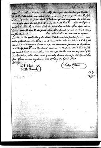
trough T, is relieved and the whole strip falls upon the circular eye Z of the trough S of the bridge, and while it serves as a new fulcrum for the lever L, by the aid of which the piston head P is forced up and compresses the brick, also serves to force down the top plate T under the bridge head R. After the pressure is finished, the lever L is thrown back, the bridge head is taken off as before and on bearing down the lever V, the piston head P is forced up and the brick dislodged from the mould.
Now what I claim as new and as my own invention, is the application of the bridge S.R.S. and the peculiar form and application of the main lever (L) and its connexion with the bridge S.R.S. by which the upward and downward pressures, i.e., the downward pressure on the fulcrum Z of the top plate T, and the upward pressure on the piston head P or its plate, are made to react on each other, also the application and arrangement of the parallel joints, other levers and governing screws to aid for this special purpose. Given under my hand this 27th day of April 1830.
Witnesses
N. S. Gillot.
R. W. Schenck
Julius Willard.
E. S.
Clyde.
1175 m. 47
Published accounts: journal notice
Notice in the monthly list of patents, with remarks
Journal of the Franklin Institute, new ser., vol. 6 (1830), p. 224 · View the page
15. For a Brick Press, called the "Bridle Brick Press;" Julius Willard, Baltimore, Maryland, June 10.
Remarks. The brick press, above named, is well described and figured, but its necessary complexity will not admit of our giving any thing like a clear idea of its structure without a drawing. The description and claim both refer, by letters, to the drawing which accompany them. The machine appears to have been well imagined, and, judging only by the evidence before us, we are prepared to hear a good account of its performances.
About this record
- Patentee
- DATAMP
- Date
- the Name and Date index of patents, DATAMP, USPTO records
- Invention
- DATAMP
- Listed in
- the Name and Date index of patents, DATAMP, USPTO records, Jim Shaw's X-patent list, the Journal of the Franklin Institute, Burke's List of Patents (1847)
- Burke's 1847 Patent Office list gives the same patent.
- Burke's 1847 Patent Office list gives a slightly different date; the date shown follows the standard lists.