

Drawings and documents
USPTO scan
The patent as scanned by the USPTO
-
 Page 1
-
 Page 2
-
 Page 3
-
 Page 4


U.S. Patent and Trademark Office · Google Patents
Show the transcription Hide (1,269 words)
Machine transcription (LightOnOCR) of the pages as scanned by the USPTO, most of them the handwritten copies made when the records were restored after the 1836 fire. Not checked; it can misread handwriting, so compare it with the scan.
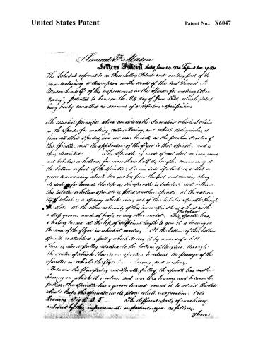
Page 2.
United States Patent
Patent No.: X6047
Samuel P. Mason
Letters Patent dated June 24, 1830. Filed Dec. 29, 1829.
The Schedule referred to in these Letters Patent and making part of the same containing a description in the words of the said Samuel P. Mason himself of his improvement in the “Spinder for making Cotton Yarn,” patented to him on the 24th day of June 1830, which patent being hereby cancelled on account of a defective specification.
The essential principle which constitutes the invention which I claim in the Spinder for making Cotton Yarn, and which distinguishes it from all other Spinders now in use, consists in the peculiar structure of the Spindle, and the application of the flyer to that Spindle, and is thus described:
The Spindle is made of cast steel, or iron, round and tubular or hollow, for more than half its length, commencing at the bottom or foot of the Spindle. On one side of which is a slot or groove commencing about two inches from the foot and running along its side as far towards the top as the Spindle is tubular, and within. The tubular or hollow Spindle is fitted another Spindle, at the extremity of which is a spring which rises out of the tubular Spindle through the slot. At the other extremity of this inner Spindle is a head with a deep groove, made of brass or any other metal. This Spindle has a bearing turned at the top, of sufficient length to give it a bearing on the nose of the flyer in which it revolves. At the bottom of this hollow Spindle is attached a pulley which drives it by means of a belt. There is also a pulley attached to the bottom of the flyer, through the centre of which there is an aperture to admit the passage of the Spindle on which the flyer has a bearing, and revolves.
Between the flyer pulley and Spindle pulley, the Spindle has another bearing on which it revolves, and near this bearing and between the pulleys, the Spindle has a groove turned round it, to admit the slide which keeps the Spindle in its place while in operation. Vide Drawing, Fig. 2, 3, 5.
The different parts of machinery embraced by this improvement are particularly described as follows.
Page 3.
United States Patent
Patent No.: X6047
is a frame of wood or iron to support the several parts. On the top of one of the sides is a set of fluted rollers, with top rollers. The first motion of the machine is produced by belting on to a pulley which is firmly fixed to the front roller and the motion is continued to the middle and back rollers by means of gearing, on a level with the rollers at right angles to them, are horizontally placed the spindles and flyers, with their bearings at both ends on two cross girts. From one end of the front roller is geared at right angles a shaft lying horizontally and parallel with the spindles; near the end and on this shaft is a pulley which gives motion to the flyers by means of a belt running over, and under alternately, the flyer pulleys. From the other end of the front roller is also geared a horizontal shaft at right angles to the rollers, upon which is a wooden cone which I term the driving cone; parallel with this is another cone which receives its motion from the driving cone by means of a belt running from the driving cone under a friction pulley. At the extremity of the receiving cone shaft is a pulley which drives the spindles by means of a belt running over and under the spindle pulleys. On the driving cone shaft is a pulley which gives motion by means of a belt, to a shaft lying horizontally under the driving cone. On this shaft is a cylinder upon which lies a bobbin with a spindle or shaft running through its barrel; on one end of which is a worm playing into the teeth of a wheel upon an upright shaft. Near the bottom of this shaft, is geared a horizontal shaft at right angles, which is geared at the other end into a perpendicular shaft, placed in the center of a carriage which moves on a rail way under the spindles. On this perpendicular shaft is a half wheel which goes into two racks fixed upon the carriage and playing alternately in each rack gives the carriage its back and forward motion. Parallel to the bobbin upon the cylinder, is another bobbin filled with end of the same size as the moving shaft you wish to make. This end is taken up when the machine is in motion by the bobbin on the cylinder and thus, as it fully moves slower, and moves the carriage and also the slides within the spindles, which are attached to the
Page 4.
United States Patent
Patent No.: X6047
to the carriage to move slower, and thus enables the flyer to lay the roving in regular layers on the spools as they traverse back and forth on the spindles by means of the traverse motion of the carriage. There is a sliding rack with graduated teeth placed between the horizontal cones, with a friction pulley at one end. Above this rack are two hammers with arms running downwards by the side of the horizontal shaft, and on this shaft is a dog or projecting finger. Upon every half revolution of this shaft the dog presses against the hammer arm thereby raising the hammer from the tooth of the rack above and permitting it to move along by means of a weight attached to one end by a belt or cord, and thus, more or less, the cone belt which runs under the friction pulley until the rack is checked by the other hammer which catches into the next tooth of the rack, when the dog or projecting finger relieves the arm it is moved back to its former position by a spring on the opposite side of the arm which presses it back and brings the hammer down upon the rack.
The bobbin is brought in contact to the spindles and passing over the drawing rollers, and thence to the nose of the flyer and of the guide, along the inner side of the flyer and receives its level, and is then laid in layers on the spools until they are filled.
The slide which secures the spindles in their places when the machine is in operation is drawn back and the spindles are then drawn back from the nose of the flyer a sufficient distance to admit of taking off the spools of roving, and a new set of spools put on. The spindles are then pushed back to their places and secured by the slide or catch and the regulator bobbin, reversed; the cone belt and rack are also slipped forward.
Instead of the regulator bobbin and cord, cones may be substituted to perform the same office, and Gear Wheels instead of pulleys and belts may be used to drive the spindles and flyer box and the form of this is intended equally to embrace all variations in which the spindles may of my construction may be placed whether diagonally or perpendicularly or diagonally.
Winston {Howard D. Morrison} (1261 words) {Arthur J. Mason}
Published accounts: journal notice
Notice in the monthly list of patents, with remarks
Journal of the Franklin Institute, new ser., vol. 6 (1830), p. 231 · View the page
36. For Making Roving in Cotton Spinning, by means of a machine called a "Speeder;" Samuel P. Mason, Leesville, Middlesex county, Connecticut, June 24.
Remarks. Those acquainted with cotton spinning are aware that several patents have been taken for speeders. The specification of the present refers throughout to the drawings, which are complex. There is no claim, and in such an apparatus this appears to be an essential defect.
Published accounts: journal notice
Notice in the monthly list of patents
Journal of the Franklin Institute, new ser., vol. 7 (1831), p. 256 · View the page
47. For an improvement in the mode of making Cotton Roving; Samuel P. Mason, Leesville, Middlesex county, Connecticut. Patent first issued June 24th, 1830.
About this record
- Patentee
- DATAMP
- Date
- the Name and Date index of patents, DATAMP, USPTO records
- Invention
- DATAMP
- Listed in
- the Name and Date index of patents, DATAMP, USPTO records, Jim Shaw's X-patent list, the Journal of the Franklin Institute, Burke's List of Patents (1847)
- Burke's 1847 Patent Office list gives the same patent.