

Drawings and documents
USPTO scan
The patent as scanned by the USPTO
-
 Page 1
-
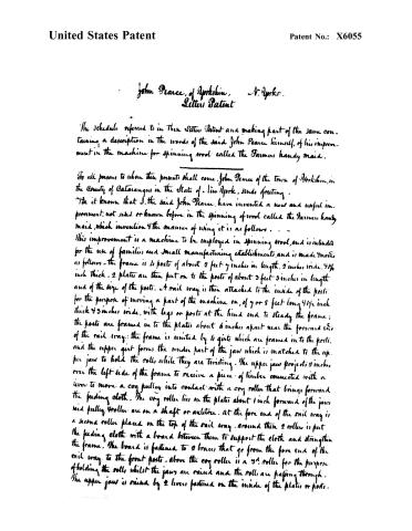 Page 2
-
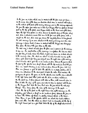 Page 3
-
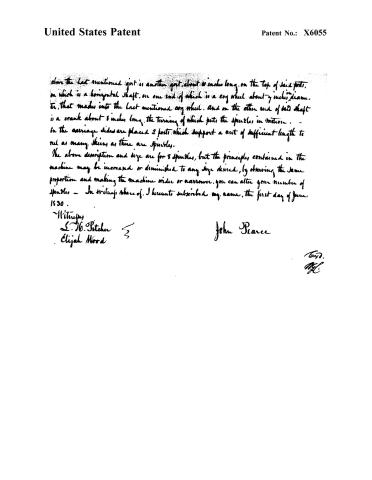 Page 4


U.S. Patent and Trademark Office · Google Patents
Show the transcription Hide (1,140 words)
Machine transcription (LightOnOCR) of the pages as scanned by the USPTO, most of them the handwritten copies made when the records were restored after the 1836 fire. Not checked; it can misread handwriting, so compare it with the scan.
Page 2.
United States Patent
Patent No.: X6055
John Pearce, of Yorkshire, N. York.
Letters Patent
The Schedule referred to in their Letters Patent and making part of the same containing a description in the words of the said John Pearce himself, of his improvement in the machine for spinning wool called the Farmer’s handy maid.
To all persons to whom these presents shall come, John Pearce of the town of Yorkshire, in the County of Catawga in the State of New York, sends greeting.
Be it known that I, the said John Pearce, have invented a new and useful improvement, not used or known before, in the spinning of wool called the Farmer’s handy maid, which invention and the manner of using it is as follows.
This improvement is a machine to be employed in spinning wool, and is intended for the use of families and small manufacturing establishments, and is made more as follows: the frame is 4 posts of about 2 feet 9 inches in length, 2 inches wide, 4/8 inch thick. 2 plates are then put on to the posts of about 3 feet 3 inches in length and of the size of the posts. A rail way is then attached to the inside of the posts for the purpose of moving a part of the machine on, of 7 or 8 feet long 4/8 inch thick 4 3 inches wide, with legs or posts at the hind end to steady the frame; the posts are framed in to the plates about 6 inches apart near the forward end of the rail way; the frame is united by 4 girts which are framed in to the posts, and the upper girt forms the under part of the jaw which is matched to the upper jaw to hold the rolls while they are twisting. The upper jaw projects 2 inches over the left side of the frame to receive a piece of timber connected with a lever to move a cog pulley into contact with a cog roller that brings forward the feeding cloth. The cog roller lies on the plates about 1 inch forward of the jaw and pulley rollers are on a shaft or axle tree. At the fore end of the rail way is a second roller placed on the top of the rail way. Around these 2 rollers is put the feeding cloth with a board between them to support the cloth and strengthen the frame. The board is fastened to 2 braces that go from the fore end of the rail way to the front posts. Above the cog roller is a 3/4 roller for the purpose of holding the rolls whilst the jaws are raised and the rolls are passing through. The upper jaw is raised by 2 levers fastened on the inside of the plates or posts.
Page 3.
United States Patent
Patent No.: X6055
In the jaws are 2 pins which come in contact with the fore ends of 2 levers — on the under side of the levers are shoulders which come in contact with 2 pieces on the outside of the posts of the moving carriage, and as the carriage approaches the jaws, the upper jaws raises and is held by 2 triggers that are fastened to 2 short posts on the top of the plates. Said triggers catch on the hind end of the levers. Upon the left hand plate is a slide secured by opposite pieces, at the fore end of said slide is attached a cord that runs to the fore end of the frame with a weight on the end. Said cord goes round the cog pulley 44000 to bring forward the roll carriage by an arm attached to the moving carriage, and when said carriage is drawn back it comes in contact with the triggers and disengages them from the levers & the jaws close on the rolls.
The rail way is about 15 inches from the floor and is grooved for the carriage to run on. The construction of the carriage is as follows, the sides are about 2½ feet long, 2 inches wide & 1¼ thick; 2 girts, and moves on 4 wheels attached to the carriage sides. The wheels are about 3 inches diameter and one of the above girts about 2 feet long and projects over the right side of the carriage about 10 inches, said girt lies in an inclined form towards the jaws on which the foot of the spindle and shaft stands, with the top inclined toward the jaws. There are 3 posts standing in an inclined form towards the jaws. Into 2 of them are framed a girt to hold the spindle in a proper position, and 2 arms are attached to the said posts to hold the roller that contains the guidecons, to guide the yarn on to the spindle, and another arm is attached to the left hand post that pulls into the slide, as above mentioned.
On the posts are 2 pieces placed with holes in them, with moveable pins in them to alter the size of the yarn, and also to come in contact with the pins in the triggers that hold the levers that raise the jaws, whilst the rolls pass through. There braces from the sides of the carriage to the posts.
Near the top of the posts on the right-hand side of the carriage on the projecting girt stands a shaft in an inclined form towards the jaws, on or near the bottom of which is a pulley around which is the band. From thence it goes to the spindle, which are about 2½ inches distance from each other, and the wheels are about 1 inch in diameter. At the top of the right hand post is a girt that holds the top of the shaft about 4 inches
Page 4.
United States Patent
Patent No.: X6055
above the last mentioned post is another post, about 10 inches long, on the top of said post, on which is a horizontal shaft, on one end of which is a cog wheel about 7 inches in diameter, that meshes into the last mentioned cog wheel. And on the other end of said shaft is a crank about 8 inches long, the turning of which puts the spindles in motion. In the carriage sides are placed 2 posts which support a rail of sufficient length to run as many spindles as there are spindles.
The above description and size are for 8 spindles, but the principles contained in the machine may be increased or diminished to any size desired, by observing the same proportion and making the machine wider or narrower, you can alter your number of spindles — In witness whereof, I hereunto subscribed my name, the first day of June 1830.
Witnesses
L. H. Pitchen
Elijah Wood
John Pearce
Toryd.
M.C.
Published accounts: journal notice
Notice in the monthly list of patents, with remarks
Journal of the Franklin Institute, new ser., vol. 6 (1830), p. 234 · View the page
44. For a Machine for Spinning Wool, by eight spindles, or more, called "The Farmer's Handy Maid;" John Pierce, Yorkshire, Cataraugus county, New York, June 30.
Remarks. There has been a long truce with the "Domestic Spinners," although patents for such machines were issued in numbers two or three years since. Should the present application be the harbinger of an improving state in our household manufactories, we bid it welcome, whether new or old, as we love the bearers of good tidings.
DATAMP: illustration
Illustrations from DATAMP
DATAMP (Directory of American Tool and Machinery Patents), via the Internet Archive · Archived DATAMP page
About this record
- Patentee
- DATAMP
- Date
- the Name and Date index of patents, DATAMP, USPTO records
- Invention
- DATAMP
- Listed in
- the Name and Date index of patents, DATAMP, USPTO records, Jim Shaw's X-patent list, the Journal of the Franklin Institute, Burke's List of Patents (1847)
- Burke's 1847 Patent Office list gives the same patent.