

Drawings and documents
National Archives restored drawings: drawing
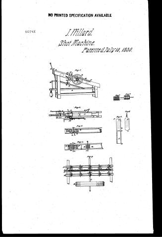
J. Willard's Patent Drawing for a Shot Machine

National Archives, Restored Patent Drawings (Record Group 241) · Full-size scan at the National Archives · Catalog record
Show the text on the drawing Hide (152 words)
Words on the drawing as machine-read by the National Archives; not checked. Useful mainly for searching.
M, hald the ihopper / kmif to clean the lid milal of the mould / Fig.2 / onto the prami / shoot for the / 20 / 5g / finished articles. / 614 lower half Pat, molds July 10-1830 / shout S for / surplus mital. / upher half handle molds. / III / Fig.3 / hopher / op / °1° / bottomless hopper. / Fig.1 / Willard's Shot Shot Machine / PatentidJuly 1830 / 22 / Fig.4 / a b hunges, linge plate in in that / S us a wooden blocch cound with / born of s which fellews under b. / tin. / So Chall place to may be / shoot. / lumm wh deverveiogo to / cuts off fins by pleasing / deliver m shot / 12 under r / Shot proteshing make Fig.9 / Fig.5 / CS / 6074-1 / Fig.6 / 111 / Te / SC / Fig." / Fig.8 / by being Learner / vieseyh grossers / Shot holerhed by being paper / in beð 2 / through and grooves fantly in and of trough / it for Date rollers / havely Mr wellers
USPTO scan
The patent as scanned by the USPTO
-
 Page 1
-
 Page 2
-
 Page 3
-
 Page 4
-
 Page 5
-
 Page 6
-
 Page 7


U.S. Patent and Trademark Office · Google Patents
Show the transcription Hide (2,036 words)
Machine transcription (LightOnOCR) of the pages as scanned by the USPTO, most of them the handwritten copies made when the records were restored after the 1836 fire. Not checked; it can misread handwriting, so compare it with the scan.
Page 1.
NO PRINTED SPECIFICATION AVAILABLE
6074X
J. Willard.
Shot Machine.
Patented July 10, 1830.
Fig. 1.
Fig. 2.
Fig. 3.
Fig. 4.
Fig. 5.
Fig. 6.
Fig. 7.
Page 2.
July 12, 1890
Julius Willard of the city & State of Baltimore,
Letters Patent. X6074
The schedule referred to in these Letters Patent and making part of the same, containing a description in the words of the said Julius Willard himself of his improvement in the machine for making shot, musket and rifle bullets called Willard's Patent Shot-machine.
To all to whom these presents shall come
Be it known that I Julius Willard of the City of Baltimore and State of Maryland have invented a new and useful machine for making shot, musket and rifle balls, called Willard's Patent Shot Machine; and that the following is a full & exact description of the construction and operation of the said machine as invented by me. The machine consists of two parts: the casting bench by which the shot or balls are first roughly formed and the Rolling machine or frame by which they are made spherical by rolling and compression. In the annexed drawings figs. 1, 2, 3 & 4 are views of the casting Bench, & its machinery, Fig. 1 being an upright view and Fig. 2 a bird's eye view of the same. It consists of a substantial wooden frame or bench; the top rails of which from an inclined plane upon which and in the space in between thereon slides the iron mould plate (P.P.) which is furnished on its under side with a rack, (noted in Fig. 1) that works in a pinion on the axle of the large cog wheel (R) which is acted on by the crank (T) of the small cog wheel (C) and causes the mould and its fixtures to move up and down the plane at the pleasure of the operator. To relieve the friction occasioned by the sliding of the mould plate either rollers or slides are placed under it as noted in Fig. 1, and Fig. 3, and 4. When the iron mould plate, which is in two pieces, more distinctly, Fig. 3, being
Page 3.
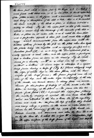
the lower part which is made fast by two lugs a, b. is a block of wood faced with sheet iron or to an iron plate, it has its upper surface fitted as seen in the figure with a convenient number of nuts each being a hemisphere of the shot or ball, that is to be moulded the lower end (B) of the block or plate, is hollowed out into a valley or throat. Fig 4. the upper part or lid of the mould which is about half the thickness of the diameter of the shot or ball, is fitted on its under side, so as to match the lower plate, and is perforated opposite to these pits with small holes or gate ways which communicate from the upper side with the hollow spheres formed by the pits in the plate when laid together the plates being also supplied with an adjusting pin (p) and a levelled point (p') so as to bring the hemispherical pits exactly opposite to each other, and the upper plate is prolonged into a lockea form as seen in the drawing Fig. 4 which serves for a handle. — I is a sheet iron box or hopper without a bottom its lower edge is attached to a square brass frame having a knife f (Fig 2) placed obliquely across the edge, of which lays in the same plane, with the lower surface of the brass frame; the frame projects over the outside of the box, and the outer edges corresponding to the sides of the mould, are turned down; or strong pieces are screwed thereon for the purpose of keeping it on the mould when the latter is moving up the plane — The frame also has two small fixed points (t, t,) to prevent the hopper from following the mould, by stopping it against the iron brace hooks H, H, which are attached to the bar or beam, D, by the regulating screws, and nuts n, n, from the top of which they branch and rising along a groove, in the inner or outer sides (as shown in the drawing) of the top parts of the bench are turned inwards, and downwards and when the beam D, is set on by the lever D, to which the weight W is suspended, just on the upper surface of the brass frame of the hopper and kept at
Page 4.
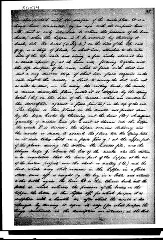
in close contact with the surface of the metal plate. G is a hand lever, connected by an axis with the compound lever M, and is only intended to relieve the pressure of the brace hooks, when the hopper is to be removed by throwing it back, into the kettle (v Fig 2) on the side of the top rail g.g. is a strip of plank, or sheet iron, attached to the outer side of the top rail and rising a few inches above it has a small apron g., at its lower end, forming together with the top surface of the rail, which is faced with sheet iron and a very narrow strip of sheet iron fixed edgewise on the rail next to the mould, a sheet to convey the shot, when not in use will be seen, — In using the casting bench, the mould is moved down the plane, until it is stopped by the spring latch (d) on the side of the mould, which was omitted in the description against a fixed pin (e) in the top of the rail. The hopper is then placed on the mould and pressed down by the brace hooks by throwing out the lever (G). A sufficient quantity of melted lead for a cast is thrown into the hopper. The crank F is turned, the hopper remains stationary and the mould is made to ascend the plane till the spring latch on its side takes hold on a fixed pin (y) at the upper part of the plane during this motion the moulds fill, and the oblique knife f. cleans the line of the mould also the distance is so regulated that the lower part of the hopper at the end of the motion projects over the short- or valley (S) and the lead which may still remain in the hopper in a fluid state runs off is caught by the boy in a table and returned to the kettle again. The lever G is then thrown back into the latch w. which relieves the pressure of the braces on the hopper, the latter is then lifted off for which purpose it is supplied with a handle, or, after which the mould is discharged by turning it upon its edge (for which purpose the things mentioned in the description are intended) on the shot.
Page 5.
formed along the top of the rails and striking it a blow or two with a stick. It may be proper to mention that a little tallow may be occasionally applied to the wheels when hot.
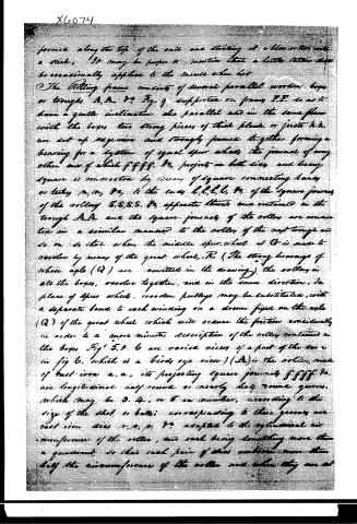
The Rolling frame consists of several parallel wooden boxes or troughs A, A, &c. Fig. 9 supported on frames I, I, so as to have a gentle inclination also parallel and in the same plane with the boxes, two strong pieces of thick plank, or joists k, k, are set up squarewise and strongly joined together forming a bearing for a system of equal spur wheels, the journal of any other one of which f, f, f, f, &c. projects on both sides and being square is connected by means of square connecting bands or tethers m, m, &c. to the ends l, l, l, l, &c. of the square journals of the rollers S, S, S, S, &c. opposite thereto and contained in the trough A, A and the square journals of the rollers are connected in a similar manner to the rollers of the next trough and so on so that when the middle spur wheel at C is made to revolve by means of the great wheel, R, (The strong bearings of whose axle (Q) are omitted in the drawing) the rollers in all the boxes, revolve together, and in the same direction. In place of spur wheels, wooden pulleys may be substituted, with a separate band to each winding on a drum fixed on the axle (Q) of the great wheel which will occasion the friction considerably.
In order to a more minute description of the roller contained in the boxes Fig. 5, 4, 6 are varied views of a part of the same in Fig. 6, which is a bird's eye view) (A) is the roller, made of cast iron a, a, its projecting square journals f, f, f, f, &c. are longitudinal half round or nearly half round grooves, which may be 3, 4, or 5 in number, according to the size of the shot or balls; corresponding to these grooves are cast iron dies r, r, r, &c. adapted to the cylindrical circumference of the roller, and each being something more than a quadrant, so that each pair of dies contains more than half the circumference of the roller and when they are set
Page 6.
X6074
37
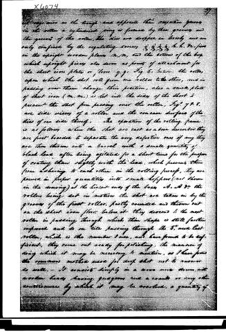
of large iron in the trough and opposite their respective grooves in the roller a cylindrical pin is formed by their grooves and the grooves of the roller, the dies are dropped in loosely and are only confined by the regulating screws 3, 3, 3, 3, h, h, &c., fixed in the upright wooden plates m, m, and the bottom of the box which upright pieces also serve as points of attachment for the sheet iron plates or floors g, g, Fig 5, between the rollers, upon which the shot roll from one roller to the other, and in passing over them change their position, also a small plate of sheet iron (m, m,) is let into the sides of the shot to prevent the shot from passing over the roller, Fig. 7 & 8. are side views of a roller and the concave surface of the dies of one side thereof. The operation of the rolling frame is as follows: when the shot are cast as above described they are first boarded to separate the very defective ones if any, they are then thrown into a barrel with a small quantity of black lead, after being agitated for a short time for the purpose of coating them slightly with the lead, which prevents them from adhering to each other in the rolling process, they are poured in proper quantities into small hoppers (not shown in the drawing) at the highest ends of the boxes A, A &c. the rollers being set in motion the shot are taken in by the grooves of the first roller, partly rounded and thrown out on the sheet iron floor, below it they descend to the next roller in passing through which their shape is still further improved and so on till passing through the 5th and last roller, which is the number I use, and have found to be sufficient, they come out ready for polishing. The manner of doing which it may be necessary to mention, as I have found the common method used for drop shot not to answer so well. — It consists simply in a move more drum, with wooden heads having grooves and a crank or any other contrivance by which it may be worked, a quantity of
Page 7.
X6074
of the shot, we put into it and a small quantity of lead, it is then turned till the shot has the desired shape after which they are taken out and hammered in the common way, and note what I claim as new and as my invention is the casting Bench and Rolling frame and their machinery as herein described applies to the purpose specified.
Given under my hand and seal this 3rd day of July 1830
Witness
Julius Willard
A. M. Latine
M. P. Elliot
207600
Published accounts: journal notice
Notice in the monthly list of patents, with remarks
Journal of the Franklin Institute, new ser., vol. 6 (1830), p. 295 · View the page
17. For a Machine for making Shot, and Musket and Rifle Bullets; Julius Willard, Baltimore, Maryland, July 10.
Remarks. The machinery referred to in the above title is intended to manufacture balls by first casting, and afterwards condensing them by rolling. Several abortive attempts have been made to manufacture bullets by pressure, so as to condense, and equalize them; the failure has not resulted from any real difficulty in accomplishing the object, but from the increase in cost. The present plan exhibits a good arrangement for the purpose, and is very distinctly described. The specification refers throughout to the drawings which accompany it, and without which no more than a general idea of the machinery can be given. The balls are first cast in moulds consisting of two iron plates, faced so as to fit closely together. The lower plate forming onehalf of the bullet, and the upper plate the other half. The thickness of the upper plate is just equal to that of the half bullet, there being a hole through it above each, for the purpose of casting. These plates are so placed as to form an inclined plane, upon a frame made for the purpose. A hopper to contain lead to fill the moulds, is made to slide over, and in contact with the upper plate, and is followed by a knife which removes all the superfluous metal. The hopper is borne down by a weighted lever, and moved by a rack and pinion. Upon being turned out of the moulds, the bullets are coated with black lead, to prevent their adhering, after which they are passed through the rolling machine. This consists of small hoppers, into which they are first put, and by which they are delivered on to grooved rollers, properly adapted to them; of these there are five, which they pass in succession, each with the grooves a little smaller than the preceding one; this number, it is said, is found sufficient to render the balls perfect. The claim is to the general arrangement of the whole of the machinery.
About this record
- Patentee
- DATAMP
- Date
- the Name and Date index of patents, DATAMP, USPTO records
- Invention
- DATAMP
- Listed in
- the Name and Date index of patents, DATAMP, USPTO records, Jim Shaw's X-patent list, the Journal of the Franklin Institute, Burke's List of Patents (1847)
- Burke's 1847 Patent Office list gives the same patent.