

Drawings and documents
National Archives restored drawings: drawing
William Clark's Patent Drawing for a Spinning Machine

National Archives, Restored Patent Drawings (Record Group 241) · Full-size scan at the National Archives · Catalog record
Show the text on the drawing Hide (302 words)
Words on the drawing as machine-read by the National Archives; not checked. Useful mainly for searching.
Shimming Jex / $2- / 118. SPINNING. / WILLIAMCARK'S / [142] Domestic. / SPINNING MACHINE / CLASSIFICATION / Patented 1st Oct !" 1830. / 6111-7 / DIVISION. / B. / D. / H. / C. / F. / J. / REFERENCES. / A, A frame, consisting of post girts: two arms, or plates, with grooves in the same, for a carriage to run on. / B, A wheel, and band, passing round a oylinder; together, with a Shaft and crank; and, also, a cog-wheel near the crank, on the inside of / the frame; which, by turning said arank, the Machine is put in operation. / C, A Cylinder, around which pass all the bands of the spindles. / D, A Carriage, on which the rolls are placed; and is moved out by means of cords attached to the same; and running in grooves, in / the tops of the plates, or arms. / E, A Cog-wheel, which meshes into the one on the shaft of the main wheel, on being raised by cords; also, a grooved wheel, attached, on / the back of the cog-wheel, around which passes a cord, and extends back to another wheel. / F, Two grooved wheels, attached together; one four, the other eight inches; around which the cord passes. / G, A board, attached to the outside of the plate, on the inside of which are cogs, which govern the roller, under which the rolls / are placed on the carriage. / H, A wire, which each end is placed in the ends of the plates; and a handle, which serves as a crank, in turning over the / spindles; that the threads may be run on them with a degree of accuracy, and dispatch. / 1, A board, morticed, in which a cog, and grooved wheels are placed. / J, A Cross bar, consisting of two posts, in which the Cylinder is placed.
USPTO scan
The patent as scanned by the USPTO
-
 Page 1
-
 Page 2
-
 Page 3
-
 Page 4


U.S. Patent and Trademark Office · Google Patents
Show the transcription Hide (1,202 words)
Machine transcription (LightOnOCR) of the pages as scanned by the USPTO, most of them the handwritten copies made when the records were restored after the 1836 fire. Not checked; it can misread handwriting, so compare it with the scan.
Page 1.
W. Clark.
Spinning Mach.
Patented Oct. 1, 1830.
Page 2.
William Clark
Letters Patent
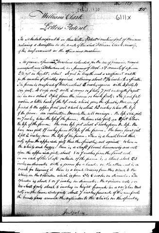
The Schedule referred to in these Letters Patent & making part of these same containing a description in the words of the said William Clark, himself of his improvement in the spinning machine
The frame of spinning machine intended for the use of families & some manufacturing establishments in spinning of Wool. It consists of a frame 2 1/2 feet in height, about 4 feet in length and a sufficient width for the number of spindles required, allowing about 2 1/4 inches to a spindle. The frame is composed of timbers about 2 inches square with 4 posts 14 feet long. 4 cross girts with 2 arms or plates 7 feet in length projecting in rear about 3 feet from the frame or back posts. The front foot incline a little back of the top end which gives the spindle, that are suspended to the upper front girt which is about 12 inches below the top of the frame, an inclination towards the rear carriage. The top side girts are 7 inches below the top of the frame; the lower side girts are 2 feet below the top of the frame. The rear top girt about 5 inches from the top. The lower rear girt 17 inches from the top of the frame, the lower front girt 2 feet 2 inches from the top of the frame. There is a board broad that rests upon the upper side girts that the spindles rest against to keep the whirly and buzzes. There is a shaft placed transversely and rests upon the upper side girts, about 8 or 9 inches from the front end. On one end of this shaft outside of the frame is a wheel about 22 inches in diameter with a groove for a band. On the other end is a crank for turning it. There is a band passing from this wheel to the whirly on the cylinder which is from 3 to 6 inches in diameter. The cylinder is about 3 or 4 inches in diameter. The cylinder rests on two short posts about 8 inches in height framed in a way's bar that rests on the lower side girts about 7 inches forward of the rear posts. The bands pass around the cylinder to the whirly on the spindles.
For 1/2 pence.
Page 3.
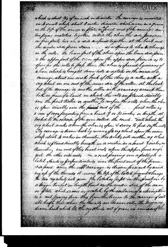
which is about 3/4 of an inch in diameter. The carriage is mounted on 4 small wheels about 2 inches diameter which moves in a groove on the top of the arm or plates in front end of the carriage are two pieces matched together, called the close the side pieces are in four parts, two on a side confined together at the back and the under side pieces serves as a spring to allow to close up on the rolls. The lower part of the close upon the lower side piece & the upper part of the close upon the upper side piece so as to open for the rolls to pass thru. The close is opened by means of a lever which is brought down into a notch in the corner of the carriage, about one inch back of the close is a roller with a cog wheel on one end of the same size of the roller. At the back end of the carriage is another roller with a camass around them both on form a band on which the rolls are placed directly over the front roller is another to confine the rolls when the close is open directly over the front end of the front roller is a row of cogs projecting from a board 9 or 10 inches in length attached to the outside of the arm called the comb. Inside which the cog wheel works when the close is open & serves to feed in the rolls. The carriage is drawn back by means of a cog wheel upon the main shaft about 4 inches in diameter. This works into another cog wheel which is placed directly beneath in a notch in a board 8 inches in diameter, one end of this board rests upon the upper front end of the quit. The other end rests on a rod passing over a pulley to a latch standing perpendicularly near the front end of the frame. As soon as the roll carriage is drawn forward by winding up of the threads it moves the top of the latch forward & brings the two cog wheels into gear. The latch is kept in this position by a bigger lever set in length fixed on the under side of the arm or plate which serves as a catch, by the assistance of a spring there is a rod passing from this frame to the carriage & pull all length thru when the threads are drawn out. The trigger is drawn back which lets the cog wheels out of gear on one side of the
Page 4.
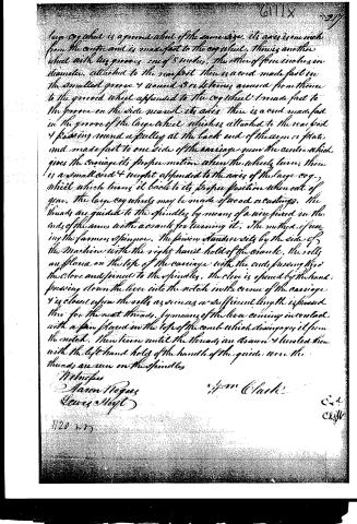
large cog wheel is a grooved wheel of the same size. Its axis is one inch from the center and is made fast to the cog wheel. There is another wheel with two grooves, one of 3 inches, the other of four inches in diameter, attached to the rear foot. There is a cord made fast in the smallest groove and wound 3 or 4 times around from there to the grooved wheel appended to the cog wheel and made fast to the groove on the side nearest its axis. There is a cord made fast in the groove of the large wheel, which is attached to the rear foot and passing round a pulley at the back end of the arm or plate and made fast to one side of the carriage near the center, which gives the carriage its proper motion when the wheels turn. There is a small cord and weight appended to the axis of the large cog wheel which turns it back to its proper position when out of gear. The large cog wheels may be made of wood or castings. The threads are guided to the spindles by means of a wire fixed in the ends of the arms with a crank for turning it. The method of using the farmer's spinner. The spinner stands or sits by the side of the machine with the right hand hold of the crank. The bobbins are placed on the top of the carriage with the ends passing through the clove and joined to the spindles. The clove is opened by the hand pressing down the lever into the notch in the corner of the carriage and is closed upon the bobbins as soon as a sufficient length is passed through for the next threads, by means of the lever coming into contact with a pin placed in the top of the comb which disengages it from the notch. Then turn until the threads are drawn and twisted then with the left hand hold of the handle of the guide, where the threads are run on the spindles.
Witnesses
Aaron Rogers
Lewis Hoyt
11/20 1847
John Clark
C. C.
C. H. W.
About this record
- Patentee
- DATAMP
- Date
- the Name and Date index of patents, DATAMP, USPTO records
- Invention
- DATAMP
- Listed in
- the Name and Date index of patents, DATAMP, USPTO records, Jim Shaw's X-patent list, Burke's List of Patents (1847)
- Burke's 1847 Patent Office list gives the same patent.