

Drawings and documents
National Archives restored drawings: drawing
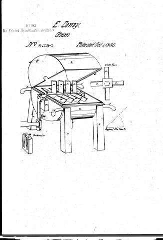
Ebenezer Dewey's Patent Drawing for a Float Wheel Churn

National Archives, Restored Patent Drawings (Record Group 241) · Full-size scan at the National Archives · Catalog record
Show the text on the drawing Hide (139 words)
Words on the drawing as machine-read by the National Archives; not checked. Useful mainly for searching.
31. DAIRY. / Rotary Churns. / Horizontal Single Dasher. / Potary Chams / Kotary / agr products / CLASSIFICATION / 6119-1 / DIVISION / Ebenerer Duwey / Hoat Wheel Churn. / Vol 10 pg 223 / 81 / Patented bet 1. 1830, / B a / Preferences. / a the lower part of the cylinder / B. the upper part of the same. / C the lip or projection / d the zabbet. / E.e.e.e. the legs. / ffff. the handles. / 12 / If the small air hole / the plug / to / i the exis of the float wheel. / K the bearing of the asis / 12 / l the crank. / m the conductor. / Side-view. / n n n Ne. floats at anangle of as degues. / angle of the floats. / Patent office 3/July 1841. / Conductor / made under the direction of the Commissioner of Patents / del: / in conformity with act of 3) march 1837. / WLSUmorth / Commissioner of Patents.
USPTO scan
The patent as scanned by the USPTO
-
 Page 1
-
 Page 2
-
 Page 3
-
 Page 4


U.S. Patent and Trademark Office · Google Patents
Show the transcription Hide (950 words)
Machine transcription (LightOnOCR) of the pages as scanned by the USPTO, most of them the handwritten copies made when the records were restored after the 1836 fire. Not checked; it can misread handwriting, so compare it with the scan.
Page 1.
6119X
No Printed Specification Available
E. Denney.
Churn.
No. 6,119-X
Patented Oct. 1, 1830.

Page 2.
No. 78
Oct 1, 1850
229.
6119x
Ebeneyer Dewey
Letter Patent
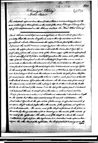
The schedule referred to in these Letter Patent unannexing part of the same containing a description in the words of the said Ebenezer Dewey himself of his improvement in the churn called the "Float Wheel Churn"
Said churn consists of a concave cylinder or barrel which opens horizontally through the centre lengthwise and is thereby divided into two equal parts which I denominate the upper & lower part of the churn. To prevent the milk & cream escaping from the churn when it is in operation the upper part is inserted or let into the lower part by a lip or projection (from the inner side of the lower edge of the said upper part) which exactly fits & fills a corresponding aspen the inner side of the upper edge of said lower part which embitting & projection are an inch or more wide so that when the churn is shut the joint between the upper & lower parts is covered by the said projection & is rendered nearly tight. At the ends of the lower part of the churn are attached 4 legs 2 upon each end 2 feet long which raise the churn a suitable height from the floor for convenience. On the sides of the churn 2 upon each part are 4 handles with which to move & to open the churn. On the lower side of one end of the churn is an inch hole with a plug or top to it through which the butter while it is let out of the same & on the top of the upper part is a small hole to permit the air to escape from the churn when it is in motion. The size of a common churn is 10 inches in diameter & 12 inches in length on the inside but these dimensions may be varied at pleasure. The float wheel by which the operation of churning is effected consists of an axis or shaft which passes through the centre of the cylinder at right angles to its diameter. The inner end of the shaft is fastened to its place in the centre by being inserted into a bearing on the centre of the inside of one end of the cylinder. The other end of the shaft to which the crank is attached projects from the cylinder 2 or 3 inches & rests upon a bearing on the other hand of the cylinder. The half of a wheel bearing is on the upper
Page 3.
324.
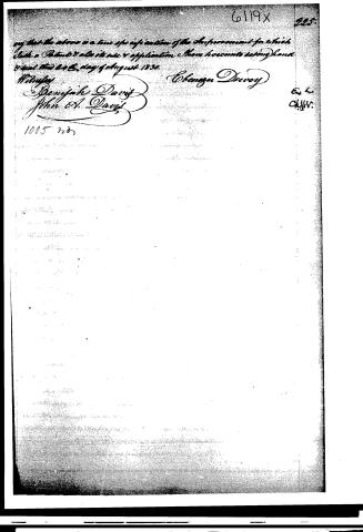
refuse & the other half in the lower part of the cylinder. On the one of the chum next to the crank & thro which the st. of refuse is placed a conductor which leads into the lower part of the cylinder. Said conductor is placed under the other end of the shaft & conveys back into the chum the cream or milk which has passed thro between the shaft & the bearing on that end of the chum. Said conductor is merely nailing & fastening in any other long piece of board 3 or 4 inches wide & 6 long grooves or flutes on one side for 3 inches in length & 2 in width at the top & terminating in a point at 4 inches from the top where a hole is cut thro into the chum & permits whatever escapes from the cylinder to pass back into the chum. Into the axis which is 4 square are inserted 4 rows of floats or paddles each row being directly opposite to another row. Each row consists of 3, 4, or more or less floats 2 inches wide & half an inch thick on the middle & an eighth of an inch thick at the edges & stand at right angles to the shaft lengthwise of the floats and in an angle of 45 degrees with the row so that when the floats lie horizontally the upper edge of each is elevated above the lower edge in an angle of 45 degrees with the surface of the cream & when the wheel is in operation the floats do not strike against the cream but partly engage and partly sideways requiring but little power to operate it & as each row of floats stands diagonally with the axis in a manner contrary or different from the row next to it each one receiving row of floats moves the cream in a direction contrary or opposite to the last preceding row & every revolution of the wheel gives the cream 4 motions besides dividing the cream as many times as there are floats in the wheel which keeps the cream or milk in continual agitation with the application of very little power. The chum is opened (cream put into it) shut again with the wheel on its place & the operation performed by means of the crank. The wheel is moved at pleasure & the chum cleansed with all imaginable ease. The wheel may be made with more or less rows of floats & with more or less floats in a row & the different parts of the chum may be varied in any respect. The method of agitating milk or cream in the manner above described may be applied to all other chums. The crank or winding shafts should be from 1 to 2 inches long according to the size of the chum. In latter
Published accounts: journal notice
Notice in the monthly list of patents, with remarks
Journal of the Franklin Institute, new ser., vol. 7 (1831), p. 11 · View the page
74. For a Churn, called the "Float Wheel Churn;" Ebenezer Deevey, Butternuts, Otsego county, New York, October 1.
Remarks. This is a sort of barrel churn, with an axis passing through it, having dashers placed upon it obliquely, and in reversed directions.
About this record
- Patentee
- DATAMP
- Date
- the Name and Date index of patents, DATAMP, USPTO records
- Invention
- DATAMP
- Listed in
- the Name and Date index of patents, DATAMP, USPTO records, Jim Shaw's X-patent list, the Journal of the Franklin Institute, Burke's List of Patents (1847)
- Burke's 1847 Patent Office list gives the same patent.