

Drawings and documents
National Archives restored drawings: drawing
A. B. Quinby's Patent Drawing for a Mode of Preventing Explosions in Steam Engines

National Archives, Restored Patent Drawings (Record Group 241) · Full-size scan at the National Archives · Catalog record
Show the text on the drawing Hide (368 words)
Words on the drawing as machine-read by the National Archives; not checked. Useful mainly for searching.
In this Drawing A.B.C. represents the Boilen / blass 31- Safety Valves, / Awindey del forward or backward As in the other banch them is Dimitar, / D the lube containing the mereary fthe floot; pisa a past / just, by which the alam be made to go off at a lower, or higher, / having a crop near the top of it, and on this is Gastened the circular / plato of brass or sher metal for the Dial; n is a fer Hey or soller: / A.B.QUINBY'S / temperature E. is a tube offen at top, for containing mercury oil, having / which and happ and bock key: un Ais tube immened in the mercury / the index; yn is a chain or cord fastened to the top fither / or oil, Permometer is put, to be used by the person who has control fither / float, and passing over the pulley W is a weight hung upon / the branch of the chain or cord which passes over the puttey in: / Mode of preventing explosions in the steam boilers. / machine for showing the temperature, in ascertaining whether the machine / is jet right, or whether the indey correctly points out the temperature of ther / this weight W besides assisting in moving the index, is designed / to lett off the a lami apparatus. Mg in the chain or cord there is a / Patented Oct. 1st $830 / Heam in the loiser. / by which the branch y n can be longthened or shortened and / vol 10 hage 471. / A.B.,Duintry / 136. valves. / March 3rd. / LASSIFICATION / [148] Safety. #1- / 6157/r-t / DIVISION. / up / Washington DC County }53 / On this 14th olay of March 1838 before the subscriber, a Sustice of the peace in and forthe said County, personally appeared Aaron B Duinly / Patent of the United States were granted to him, dated the 1ⁿday of October 1830, and that the annexed Drawing is, as he verily believes, atree delimiation of / the State of Perrnsylvania, and made solemn oathy, that he is the inventor, of a mode of preventing explosing of Steam boiley, for which Letter / one of the modes contemplated in the said Letters Patent / swom before / AlementaMorte S. Seuce
USPTO scan
The patent as scanned by the USPTO
-
 Page 1
-
 Page 2
-
 Page 3
-
 Page 4
-
 Page 5
-
 Page 6
-
 Page 7
-
 Page 8


U.S. Patent and Trademark Office · Google Patents
Show the transcription Hide (2,290 words)
Machine transcription (LightOnOCR) of the pages as scanned by the USPTO, most of them the handwritten copies made when the records were restored after the 1836 fire. Not checked; it can misread handwriting, so compare it with the scan.
Page 2.
United States Patent
Patent No.: X6157
Titus Preston
Letters Patent
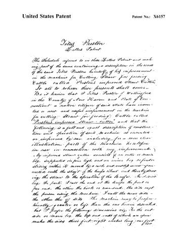
The Schedule referred to in these Letters Patent and making part of the same containing a description in the words of the said Titus Preston himself of his improvement in the machine for Cutting Straw for feeding Cattle called "Preston's improved Straw Cutter".
To all to whom these presents shall come—
Be it known that I Titus Preston of Wallingford in the County of New Haven and State of Connecticut a native citizen of said State have invented a new and useful improvement in the machine for cutting Straw for feeding Cattle called "Preston's improved Straw Cutter" and that the following is a full and exact description of construction and operation of said machine as invented or improved by me, including for a more clear illustration, parts of the machine heretofore in use in connection with my improvements.
My improved straw cutter consists of an outer or main box, supported on four legs, and an inner box or feeder sliding within it, moved by a rack and endless screw connected with the shaft of the knife wheel, and thereby drawing the straw to the operation of the knife. In describing the parts, I call the end at the knife the front or fore end, the other the back or rear end, the side next the person using the machine I call the near side—the other the off side. The machine may be proportionally greater or less than the one herein described, but I prefer the following dimensions viz: for the outside or main box, the top and ends of which are open, make the sides three feet eight inches long, one foot two
Page 3.
United States Patent
Patent No.: X6157
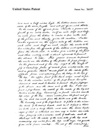
two and a half inches high, the bottom seven inches wide of the same length, and all 7/8 of an inch thick. On the inside of the off-side piece I make a groove one fourth of an inch wide, half an inch deep and half an inch from the bottom to receive a pin on the side of the frame and thereby guide its motion. I also make a groove in the upper side of the bottom an inch wide and half an inch deep, the centre to be two inches from the off-side of the bottom and extending from the back end, to within five inches of the front and there ending with a slant upwards to permit the drawer to rise. This groove is made to permit the racks on the bottom of the frame to pass freely. On the forward end of the box, next to the knife, I fix a cramping piece of wood five inches wide, one and a quarter thick made fast to the inside of the off-side piece and extending from the bottom to the top of the box. The upper part of the back edge must be fitted to the circular motion of the prop board, hereafter described and must be beveled to permit the free passage of the drawer near the same end of the box. I also suspend a prop board, the width of the inside of the box and thirteen inches long, traversing on pivots inserted near the top edge of the box, eleven inches from the front end of the box and one inch from the back end of the board. The traversing end of the prop board is fitted to the circular level of the cramp board, and on it is fixed a block an inch and a half thick and near the lower back edge of that is attached an iron dog or latch 2½ inches long, playing into a circular rack of cast-iron such its thickness into the inside of the near side of the box and descending six inches from the top with cogs, one quarter of an inch from centres. The use of the cramping piece
Page 4.
United States Patent
Patent No.: X6157
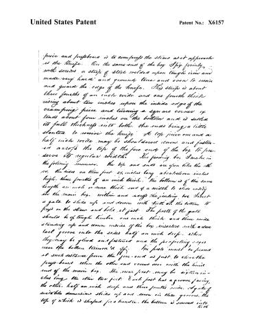
piece and prefboard is to compress the straw as it approaches the knife. On the same end of the box I fix firmly, with screws, a strip of steel welded upon tough iron and made very hard and ground true and even to receive and guard the edge of the knife. This strip is about three fourths of an inch wide and one fourth thick rising about ten inches upon the inside edge of the cramming piece and turning a square corner it tends about four inches on the bottom and is setted its full thickness into both. The ends being a little slanted to receive the knife. A top piece one and a half inch wide may be shouldered down and fastened across the top of the fore end of the box to preserve its regular width. The feeding box I make in the following manner. The top and ends are open like the other, the sides are three feet 2½ inches long, about eleven inches high, three fourths of an inch thick. The bottom is of the same length as inch or more thick and of a width to slide easily into the main box, within and across the feeding box. I erect a gate to slide up and down with teeth on the bottom to press on the straw and hold it fast. The posts of the gate should be of tough timber, one inch thick and three wide standing up and down inside of the box, inserted with a dovetail groove into the sides half an inch deep, where they may be glued and fastened and the projecting edges near the bottom trimmed off. The posts must be placed at such distance from the fore-end as just to clear the prefboard when the other end comes over with the hind end of the main box. The near post may be sixteen inches long, the other two feet. Each post has a groove facing the other, half an inch deep and three fourths wide. A gate of suitable dimensions slides up and down in these grooves, the top of which is shaped for a handle, the bottom is screwed into both
Page 5.
United States Patent
Patent No.: X6157
teeth to hold in the straw. I then fit into the off gate post adjoining the groove and making part of the back side of it a rack seven and a half inches long), the lower end to be 9½ inches from the bottom, it may be half an inch square and set in the depth of the groove and there fastened with screws the cogs or teeth a quarter of an inch apart. The under side square, a dog four inches long is fixed on a pivot near the bottom of the gate to play into the rack and thus hold fast the pressure of the gate upon the straw. A hook from one gate post to the other secures the box from spreading. A suitable handle is also attached to the rear corner of the rear end of this box to raise that end, and draw back the box as occasion may require and the upper corners of the forward end of the feeding box are slanted off to prevent their interference with the press board. To prevent the feeding box from rising, I drive an iron cog or pin a quarter of an inch in diameter into its off side half an inch back from the free end and half an inch from the bottom leaving half an inch of its length projecting to enter and slide in the groove made to receive it in the side of the main box. This pin or cog passes through an iron plate three inches long, sunk in and fastened to the side. The under corner of the plate and of the box are rounded off to permit the rear end of the box to be raised without straining on the cog. A movable check pin may be inserted along the groove to prevent the feeding box being driven back so far as to ungear the machinery. The feeding box when drawn back rests on a support extending from the rear of the main box about one foot placed a little obliquely to avoid the screw wheels but level with the upper side of the bottom. The feeding box is moved forward by a screw wheel made fast on the rear end of the main shaft playing into a rack on the under side of the feeding box. This rack I make of cast iron two feet six inches long with suitable bearings to fasten
Page 6.
United States Patent
Patent No.: X6157
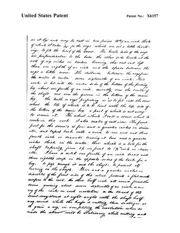
on it by) and may be cast in two pieces 1/8" of an inch thick of which I take 1/16" for the cogs which are set a little beveling to fit the level of the screw. The bevel side of the cogs are perpendicular to the base, the other side bevels at the rate of six inches in twelve, leaving the cut and left than one eighth of an inch and the space between the cogs a little more. The distance between the cogs from the center to center seven sixteenths of an inch. This rack is let into the under side of the bottom of the feeding box about one fourth of an inch directly over the center of the shaft, and over the groove in the bottom of the main box. The teeth or cogs projecting so as to fit into the screw wheel the top of which is to be level with the top side of the bottom of the main box a part of which is cut away to receive it. The wheel which I call a screw wheel to work in this rack I also make of cast iron. The front part for the screw is four and a quarter inches in diameter and tapers back with a curve to one and one three fourth inch in diameter leaving it two and a quarter inches thick in the center. This wheel is a hole for the shaft tapering from 1/4" in front to 1/8" inch in diameter. I have a notch one fourth of an inch broad and three eighths deep in the opposite sides of the back for a key to pass through it and the shaft to prevent it turning on the shaft. Three and a quarter inches in diameter of the front side of this wheel presents a flat smooth surface to the rail, the other half inch all round forms the screw gaining about seven sixteenths of an inch, or one cog of the rack on each revolution or the thread of this screw may stand at right angles with the shaft half way round, while the knife is cutting, then so oblique as to gain a cog, in completing the revolution when so made the straw will be stationary while cutting and
Page 7.
United States Patent
Patent No.: X6157
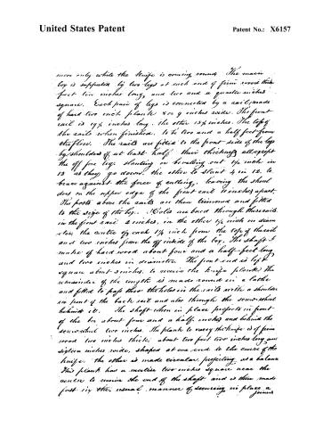
move only while the knife is coming round. The main box is supported by two legs at each end of firm wood that is four feet ten inches long, and two and a quarter inches square. Each pair of legs is connected by a rail made of hard two inch plank 8 or 9 inches wide. The front rail is 19½ inches long, the other 15½ inches. The tops of the rails when finished, to be two and a half feet from the floor. The rails are fitted to the front side of the box by shoulders of at least half their thickness all except the off fore leg, slanting or beveling out 1½ inch in 13 as they go down, the other to slant 4 in 12, to brace against the force of cutting, leaving the shoulders on the upper edge of the front rail 11 inches apart. The posts above the rails are then trimmed and fitted to the size of the box. Holes are bored through these rails, in the front rail 2 inches, in the other 1½ inch in diameter, the centre of each 1½ inch from the top of the rail and two inches from the off inside of the box. The shaft is made of hard wood about four and a half feet long and two inches in diameter. The front end is left square about 3 inches, to receive the knife plank. The remainder of the length is made round in a lathe and fitted to pass through the holes in the rails with a shoulder in front of the back rail and also through the screw wheel behind it. The shaft when in place projects in front of the box about four and a half inches and behind the screw wheel two inches. The plank to carry the knife is of firm wood two inches thick, about two feet two inches long and sixteen inches wide, shaped at one end to the curve of the knife. The other is made circular, projecting as a balance. This plank has a mortise two inches square near the centre to receive the end of the shaft and is then made fast in the usual manner of securing in place a joint.
Page 8.
United States Patent
Patent No.: X6157
Knife and for these jointly and severally, I claim an exclusive right and pray that the same may be secured to me by Letters Patent. In testimony whereof I set my hand and seal this twenty ninth day of June 1830.
Witnesses
Cheney Baldwin
Simon Baldwin
Filed
Published accounts: journal notice
Notice in the monthly list of patents, with remarks
Journal of the Franklin Institute, new ser., vol. 7 (1831), p. 3 · View the page
50. For a Machine for Cutting Straw; Titus Preston, Wallingford, New Haven county, Connecticut, October 1.
Remarks. The description of this machine is of considerable length, entering into a minute description of all its parts, both new and old. Its general structure is similar to many long known straw cutters. The specification ends as follows. " I do not, however, claim the whole machine herein described, as my invention. But I do claim as my invention and improvement, the feeding box, and its appendages, particularly the rack and screw wheel, as above described. The gate with its several appendages, and the mode herein described for fastening the plank upon the shaft; and the screws to regulate the knife. And for these, jointly and severally, I claim an exclusive right." The cutter is a curved revolving knife, fastened to a plank by means of screws, with check screws to set it at the proper distance from the plank. The mode of doing this, it will be seen, is claimed; this mode, however, is well known to every machinist. The straw is drawn forward by an endless screw cut upon the back end of the shaft upon which the revolving knife is fixed. This screw takes into a rack on the bottom of a feeding box; and the straw is thus regularly drawn forward by the revolution of the knife.
About this record
- Patentee
- DATAMP
- Date
- the Name and Date index of patents, DATAMP, USPTO records
- Invention
- DATAMP
- Listed in
- the Name and Date index of patents, DATAMP, USPTO records, Jim Shaw's X-patent list, the Journal of the Franklin Institute, Burke's List of Patents (1847)
- The National Archives' catalog gives the name differently.
- Burke's 1847 Patent Office list gives the same patent.
Shaw: lists Quimby, A. B. here as 6157½