

Drawings and documents
USPTO scan
The patent as scanned by the USPTO
-
 Page 1
-
 Page 2
-
 Page 3
-
 Page 4
-
 Page 5
-
 Page 6
-
 Page 7
-
 Page 8
-
 Page 9
-
 Page 10


U.S. Patent and Trademark Office · Google Patents
Show the transcription Hide (4,022 words)
Machine transcription (LightOnOCR) of the pages as scanned by the USPTO, most of them the handwritten copies made when the records were restored after the 1836 fire. Not checked; it can misread handwriting, so compare it with the scan.
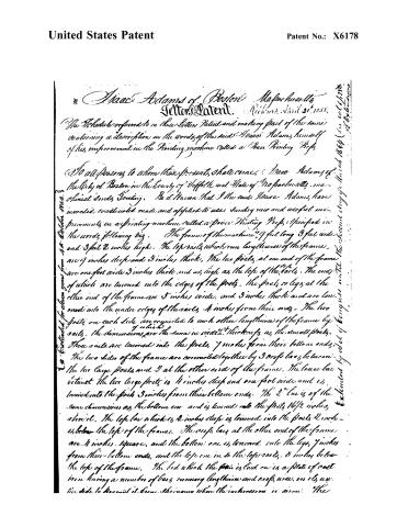
Page 2.
United States Patent
Patent No.: X6178
Isaac Adams of Boston, Massachusetts
Letter Patent. Richmond, April 26th, 1858.
The Schedule referred to in these Letters Patent, and making part of the same, containing a description on the words of the said Isaac Adams, himself of his improvement in the Printing machine called a Power Printing Press.
To all persons to whom these presents shall come, Isaac Adams of the City of Boston in the County of Suffolk and State of Massachusetts, mechanic sends Greeting. Be it known that I the said Isaac Adams, have invented, constructed, made and applied to use, sundry new and useful improvements in a printing machine called a Power Printing Press, specified in the words following viz.
The frame of the machine is 9 feet long 3 feet wide and 3 feet 2 inches high. The top rails which run lengthwise of the frame, are 9 inches deep and 3 inches thick. The two posts at one end of the frame are one foot wide 3 inches thick and as high as the top of the rails. The ends of which are tenoned into the edges of the posts. The posts or legs at the other end of the frame are 5 inches wide, and 3 inches thick and are tenoned into the under edges of the rails 4 inches from their ends. The two posts on each side are connected to each other lengthwise of the frame by rails. The dimensions are the same in width & thickness as the small posts. These rails are tenoned into the posts 7 inches from their bottom ends.
The two sides of the frame are connected together by 3 cross bars between the two large posts and 2 at the other end of the frame. The lower bar between the two large posts is 4 inches deep and one foot wide and is tenoned into the posts 3 inches from their bottom ends. The 2nd bar is of the same dimensions as the bottom one and is tenoned into the posts 16½ inches above it. The top bar which is 2 inches deep is tenoned into the posts 2 inches below the top of the frame. The cross bars at the other end of the frame are 4 inches square, and the bottom one is tenoned into the legs 7 inches from their bottom ends, and the top one is to the top rails, 5 inches below the top of the frame. The bed which the form is laid on is a plate of cast iron having a number of bars running lengthwise and cross wise, on its upper side to keep it from shrinking when the impression is given. The
Extended for eleven years from 4th October 1858.
Extended by act of Congress until the Second day of March 1864 (See vol. 21, p. 288 of Statutes at Large).
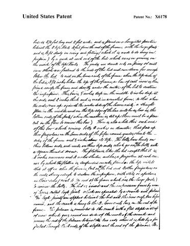
Page 3.
United States Patent
Patent No.: X6178
bed is 2½ feet long and 2 feet wide, and is placed in a horizontal position behind the 2 large rails 4 feet from the end of the frame, with the large posts and is kept steady in rising and falling (which it is made to do every instant) by a guide at each end of the bed which runs in grooves on the inside of the top rails. The guides are small rods on pieces of cast iron which are fastened to the ends of the bed and run down far enough below the bed to rest on the lower rails of the frame. When the top side of the bed is 5½ inches below the top of the frame, a bar of cast iron is then placed across the frame and directly under the center of the bed to sustain the impression. This bar is 5 inches deep in the middle, 6 inches deep at the ends, and 2 inches thick and is made in a crooked form, so that when the ends come up against the under side of the lower rails, a straight place in the middle and on the top edge of the bar will be as low as the bottom ends of the posts (when the machine is set up there must be a floor cut in the floor to receive this bar). There is also a hole through each end of this bar which receives bolts 2 inches in diameter, that pass up through projections on the lower ends of the before-named guides, close to the sides of the frame and 3 inches above its top. The bolts have heads on their bottom ends, and nuts on their top ends which go on the bolts with a square threaded screw. The platform is like the bed except that it is 4 inches narrower and 4 inches shorter, and has a projection at each corner by which the platform is suspended on rods placed on the top rails to slide it off or when the form is put on the bed and the two projections on the ends strong enough to sustain the impression, with slots or apertures in their sides (next to the end of the frame which has the large posts) to receive the bolts. The bed is raised and the impression given by means of levers called loge joints which are operated by a crank and pitman. The loge joints are applied behind the bed and the iron cross bar before named, and the crank is hung to the 2 lower cross bars in the end of the frame. The pitman is connected to the crank with a flat staple or strip of iron which goes round one side of the neck of the crank and receives the end of the pitman behind the two ends where it is held by a pin passed through the 2 ends of the staple and the end of the pitman. Be
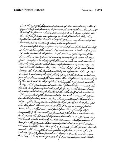
Page 4.
United States Patent
Patent No.: X6178
lived the end of the pitman and the neck of the crank there is a block of iron which is so formed as to fit on to the neck of the crank and on to the end of the pitman which is also rounded so as to form a joint on the end of the pitman corresponding with the pin which holds them together in order that the other end of the pitman may be moved up and down which it is constantly doing when in operation.
On account of its being necessary to save and loose the bed with one half of the revolution of the crank it is made eccentric 8 inches which gives 16 inches motion to the pitman in the direction of the length of the frame, this is nearly twice as much as is necessary to move the log joints therefore 10 inches of the pitman is made one inch narrower than the other part which leaves a projection on its under edge so that when the pitman has received one half of its motion towards the bed, the projection strikes an apparatus (hereafter described) and carries the log joints up until the 2 levers which compose them become nearly perpendicular, then the pitman is drawn back by the crank and the feet of the bed springs the log joints and the 2 ends which operate against each other—follow the pitman until the bed falls to its place of rest when the projection on the pitman leaves it, bearing until the crank has passed the other half of its revolution.
The narrow part of the pitman sliding into a slot made in the upper lever for that purpose, and on a pin which goes through the middle joint. Here it may be observed that the log joints are least powerful when they first begin to operate and the pitman is moving fastest towards them at that time, and fastest from them when they close, consequently (if there was nothing to prevent it) the pitman would strike so hard and the bed would stop so suddenly that it would cause the machine to shake and make considerable noise. For these reasons I have put the apparatus before named (which I shall call the declension lever) on the lower lever of the log joints for the pitman to strike against. The name of the lever signifies its property or nature, for it is almost infinitely powerful when it begins to operate and decreases to nothing. (It is made 7 inches long 2 inches wide and one inch thick)
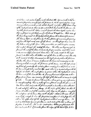
Page 5.
United States Patent
Patent No.: X6178
at its lower end, and a half an inch thick at the top end which has a rounded projection across it for the person to strike against, it is made curving about one inch in its whole length, and put on the lower lever of the log joints so that its top end will be level with the pin in the middle joint and the bottom end below the lower log, and a bar that is placed across the frame for the levers to rest on, that side of the lever being near to the log joints which forms the outside of a curve. The lever is kept in its place by a thin plate of iron one projecting out from the log each side of the lever, in these projections near to the bottom end of the lever, there are slits in which a pin moves that is put through the end of the lever. The slits are long enough to permit the end of the lever to have its proper motion and their ends are one half of an inch lower than the ends, next to the log joints) so that when the bottom end of the lever is thrown out the slits will cause it to slip downward on the log joints, when the person strikes this lever it causes it forward, the lower end remaining on its bearing which serves for the fulcrum of the lever, and the log joints are forced up gradually the resisting power receding from the fulcrum until the lever is brought to bear near its top end when it is carried along with the log joints until the impression is given when the log joints return the lower end of the lever strikes its bearing first and it operates with a progressive force, in raising the head of the bed until it comes to its place of rest. In order to prevent the machine from giving an impression in case of necessity there is a bar of iron placed across the frame on the two lower rails, and under the person, with a trundle or lever attached to each end of it which are hung to the sides of the rails, so that the person at either end of the machine who lays on the paper may push the end of one of the levers down with the foot which will raise the person high enough to clear the projection and permit it to pass, thus the rod in the upper lever of the log joints without moving them. The weight is distributed by a set of rollers on each side of the bed with an incline foundation to each side. The under compression rollers are placed so that their centers will be 1 1/2 inches from the edges of the bed & 3 1/2 below
Page 6.
United States Patent
Patent No.: X6178
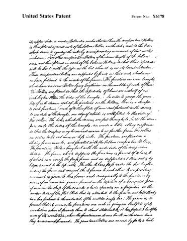
its upper side, a wooden Roller six inches shorter than the compression Rollers, is then placed against each of the bottom Rollers on the sides, next to the bed, which serve to equalize the ink by a reciprocating movement of six inches inclusive. Two other compression Rollers of the same length of the bottom ones, are then placed on each of the bottom Rollers, so that their top side will be level with the type on the bed when it is in its lowest situation. These compression Rollers are supported by pivots in their ends, which rest in bases fastened to the inside of the frame. The fountains are iron troughs, which have an iron Roller lying lengthwise in the middle of each of them. The Rollers are placed so that the top sides of them are one half of an inch higher than the sides of the troughs. In order to gauge the quantity of ink drawn up of the fountains on the Rollers, there is a scraper to each fountain, made of a thin plate of iron and fastened with screws to one side of the trough, one edge of which is well fitted to the sides of the rollers. The holes which the screws are put through, to hold the scrapers on to the sides of the troughs, are made a little oblong so as to do that the scrapers may be moved nearer to or farther from the rollers in order to let out more or less ink. The fountains are placed on a sliding frame near to, and parallel with the bottom compression Rollers. The fountain Rollers being level with the underside of the compression Rollers. The frame which supports the fountains is formed of 4 bars, 2 of which run across the proof frame and are supported at their ends by lugs secured to the top rails. The other 2 bars pass under the bed lengthwise of the frame and connect the 2 former to each other. A reciprocating movement is given to this frame and consequently to the fountains by means of an eccentric groove formed on the top side of a horizontal plate of iron on the shaft of the crank which operates on a projection on the under side of the flat Rod that is attached to the frame and held steady in a box fastened to the underside of the middle proof bar. The groove is so formed that it moves the fountains one inch in going one fourth of its revolution, where it permits them to stand still until it has passed 5 inches more of its revolution, when the fountains are drawn back in the same time they were moved forward. The fountain Rollers are moved by pulleys which
Page 7.
United States Patent
Patent No.: X6178
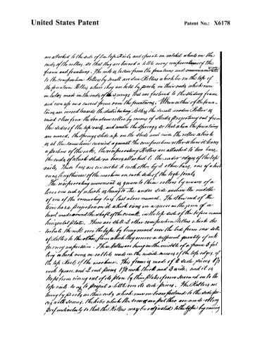
are attached to the side of the top rails, and operate on patent wheels on the ends of the rollers, so that they are turned a little every reciprocating of the frame and fountain. The ink is taken from the fountain and communicated to the composition rollers by small wooden rollers which lie on the top of the fountain rollers where they are held by pegs in their ends which run in holes made in the ends of the springs that are fastened to the sliding frame and run up in a curved form over the fountains. When either of the fountains are moved towards the distributing roller the small wooden rollers are raised clear from the fountain roller by means of studs projecting out from the sides of the top rails, and under the springs so that when the fountains are moved, the springs slide up on the studs and raise the roller which is at the same time carried against the composition roller when it leaves a portion of the ink. The reciprocating rollers are attached to two bars, the ends of which slide in boxes attached to the under edges of the top rails. These bars are connected to each other by 2 other bars, one of which runs lengthwise of the machine on each side of the loge joints.
The reciprocating movement is given to these rollers by means of a lever one end of which is hung to the under side and in the middle of one of the connecting bars last above named. The other end of the lever has a projection on it which runs in a groove in the form of a heart made round the shaft of the crank, in the top side of the before named horizontal plate. There are still 2 other composition rollers which distribute the ink over the type by being moved over the bed from one set of rollers to the other, from which they receive a sufficient quantity of ink for every impression. These rollers are hung in the middle of a frame 5 feet long which runs on rails made in the inside corners of the top edges of the top rails of the machine. This frame is made of 2 side pieces 1½ inch square, and 2 end pieces 1½ inch thick and 3 wide, and it is kept from rising out of its place by thin plates of iron screwed on to the top rails so as to project a little over its side pieces. The rollers are hung by pivots in their ends which move in boxes fastened to the side pieces with screws. The holes which the screws are put thro are made oblong perpendicular so that the rollers may be adjusted to the type by raising
Page 8.
United States Patent
Patent No.: X6178
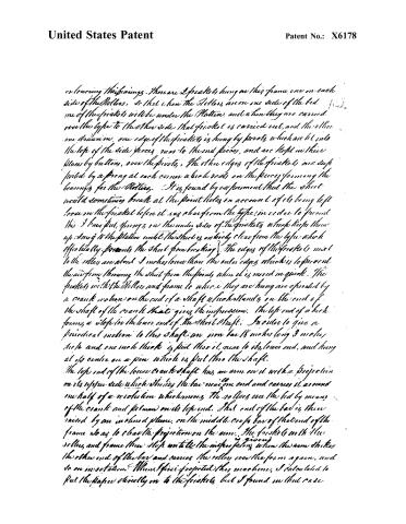
or lowering their bearings. There are 2 friskets hung on this frame, one on each side of the Rollers, so that when the Rollers are on one side of the bed, one of the friskets will be under the Platen, and when they are carried over the type to the other side that frisket is carried out, and the other one drawn in. One edge of the friskets is hung by pivots which are let into the top of the side pieces, near to the end pieces, and are kept in their places by buttons, over the pivots. The other edges of the friskets are supported by a spring at each corner which rests on the pieces forming the bearings for the Rollers. It is found by experiment that the sheet would sometimes break at the point holes on account of its being left loose on the frisket before it was clear from the type; in order to prevent this, I have put springs on the under sides of the friskets which keep them up snug to the platen until the sheet is entirely clear from the type, which effectively prevents the sheet from breaking. The edges of the friskets next to the rollers are about 2 inches lower than the outer edges, which is to prevent the air from throwing the sheet from the points when it is moved in quick. The friskets with the Rollers and frame to which they are hung are operated by a crank motion on the end of a shaft which stands on the end of the shaft of the wheel that gives the impression. The top end of a hook forms a clef for the lower end of the short shaft. In order to give a periodical motion to this shaft an iron bar 18 inches long 3 inches wide and one inch thick is put thereon, near to its lower end, and hung at its centre on a pin which is put into the shaft.
The top end of the lower crank shaft has an arm on it with a projection on its upper side which strikes the bar near one end and carries it around one half of a revolution which moves the rollers over the bed by means of the crank and fulcrum on its top end. That end of the bar is then raised by an inclined plane, on the middle cross bar of the end of the frame so as to clear the projection on the arm. The friskets with the rollers and frame then step until the impression when the arm strikes the other end of the bar and carries the rollers over the form again, and so on in rotation. When I first projected this machine, I calculated to put the paper directly on to the friskets, but I found in that case
Page 9.
United States Patent
Patent No.: X6178
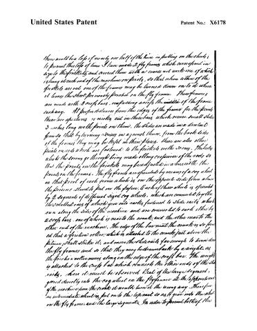
there would be a loss of nearly one half of the time in putting on the sheets; to prevent this loss of time I have made 2 fly frames, which correspond in size to the first sheets and covered them with a coarse net work one of which is hung at each end of the machine on pivots, so that when either of the first sheets are out one of the frames may be turned down on to it where it leaves the sheet previously printed on the fly frame. These frames are made with 2 cross bars, crossing across the middle of the frame each way. At proper distances from the edges of the frame for the pivots there are apertures or niches cut in these bars, which receive small slides 3 inches long with points on them. The slides are made in a dovetail form so that by turning screws in against them, from the back sides of the frames they may be kept in their places. There are also other points on rods which are fastened to the first sheets with screws. The holes which the screws go through being made oblong crosswise of the rods so that the points on the first sheets may be adjusted in a line with the points on the frames. The fly frames are operated by means of a cog wheel on that pivot of each frame which is on the opposite side from where the persons stand to put on the paper. Each of these wheels is operated by 2 segments of different sized cog wheels, which are connected together; the smallest ones of which gear into racks fastened to slide rails which run along the sides of the machine and are connected to each other by 2 cross bars, one of which is near to the crank, and the other near to the other end of the machine. The edge of the bar near the crank is so formed that a friction roller, which is attached to the crank just above the pitman, shall strike it, and move the slide rails far enough to turn down the fly frames and so that they may be drawn back by a weight, as the friction roller moves along on the edge of the cross bar. The weight is attached to the cross bar which connects the other ends of the slide rails. Here it must be observed that if the large segment, geared directly into the cog wheel on the fly frame at the opposite end of the machine from the crank it would turn it the wrong way. Therefore an intermediate wheel is put on to the top rail so as to gear into the wheel on the fly frame, and the large segment. In order to prevent both of the
Page 10.
United States Patent
Patent No.: X6178
Specification are not to be considered a rule in all cases but the machine must be proportioned to the work that is to be done with it.
The above is a Plain Specification of the whole machine, and those parts which I claim as my invention are designated as follows, viz. The combination of Stationary fly frames, with points for getting Regular by, on them with Printing Presses. The object of these fly frames is to enable the person who lays on the paper, to print one sheet while the sheet previously put on, is receiving the impression and by that means save the time which would be lost in waiting for the froshet to come out.
Furthermore I claim the apparatus described in the foregoing Specification for giving a periodical movement to the rollers & froshets, that is, I do not claim the parts separately but merely that combination of parts to produce the effect as set forth in the Specification. And furthermore I claim as my invention the application of the declination lever set forth and described in the foregoing Specification. In testimony that the above is a true Specification of my said improvements as above described I have here to set my hand and seal the 14th day of April in the year of Christ one Thousand Eight hundred and thirty.
End Wm. P.
Mg. C. Augustus Philocky
John Bryant Jr.
Ezra Adams
(4710 words)
(Granted October 4, 1890)
Published accounts: journal notice
Notice in the monthly list of patents, with remarks
Journal of the Franklin Institute, new ser., vol. 7 (1831), p. 14 · View the page
83. For sundry improvements in a Printing Machine, called a Power Printing Press; Isaac Adams, Boston, Massachusetts, October 4.
Remarks. We cannot pretend to give any description of this machine, which, in the specification, occupies ten pages, and is accompanied by large and complicated drawings. The points claimed, are, "the combination of stationary fly frames, with points for getting register by, on them, with printing presses." "The object of these fly frames, is, to enable the person who lays on the paper to point one sheet, while the sheet previously put on is receiving the impression, and by that means save the time which would be lost in waiting for a frisket to come out." An apparatus for giving a periodical movement to the rollers and friskets, as described in the specification, and the use of what the patentee calls declension levers, are also claimed.
DATAMP: illustration
Illustrations from DATAMP

DATAMP (Directory of American Tool and Machinery Patents), via the Internet Archive · Archived DATAMP page
About this record
- Patentee
- DATAMP
- Date
- DATAMP, USPTO records, Burke's List of Patents (1847)
- Invention
- DATAMP
- Listed in
- the Name and Date index of patents, DATAMP, USPTO records, Jim Shaw's X-patent list, the Journal of the Franklin Institute, Burke's List of Patents (1847)
- The sources give different dates; the date shown is the one most of them agree on.
- The Franklin Institute's journal confirms the date shown.
- Burke's 1847 Patent Office list gives the same patent.