

Drawings and documents
National Archives restored drawings: drawing
John Thorp's Patent Drawing for an Improvement on the Running Cap Spinner

National Archives, Restored Patent Drawings (Record Group 241) · Full-size scan at the National Archives · Catalog record
Show the text on the drawing Hide (138 words)
Words on the drawing as machine-read by the National Archives; not checked. Useful mainly for searching.
John They / Vol to pg.135. / 830 / 6245-4 / Improvement on the Running bap Spinner. / Patinted Nov it 1830. / Jig.1. / Fig.2. / Sig.3. / Sigh / bigs. / Sigh / ho / Informances. / a the spindle. / b.b. projecting lips. / C. the cap. see Fig. 18.6 / city. / d com mon throstle bobbin / ee channel in the bobbin / I a tube with grooves / I a collar Jee Fy 4 leotion Jy.5. / h the check Jig 18 Jy yx. / i the Knee / K.K. polished notches. / Sig i. The improved spincle. / Fy? Section of Iig. i. / Ty Seation by3 of Tis. 8. / Jig.4. frotin of Ty.5. / Sig. 6 The fiyer cap scheck / Jy % check. / This 8. Tube seenia Ji43. / Tig.8, / Patent afficithe 29th June 1840. / made under the direction of the Commitioner / of Patents in conformity with / ch. / Commissioner of Paten
USPTO scan
The patent as scanned by the USPTO
-
 Page 1
-
 Page 2
-
 Page 3
-
 Page 4


U.S. Patent and Trademark Office · Google Patents
Show the transcription Hide (1,026 words)
Machine transcription (LightOnOCR) of the pages as scanned by the USPTO, most of them the handwritten copies made when the records were restored after the 1836 fire. Not checked; it can misread handwriting, so compare it with the scan.
Page 1.
PATENTED NOV. 11, 1830.
6245X J. THORP.
MACHINERY FOR SPINNING AND IN SPINNING COTTON YARNS.

THE NORRIS PETERS CO., PHOTO-LITHO., WASHINGTON, D.C.
Page 2.
No. 6745
Nov. 11, 1830
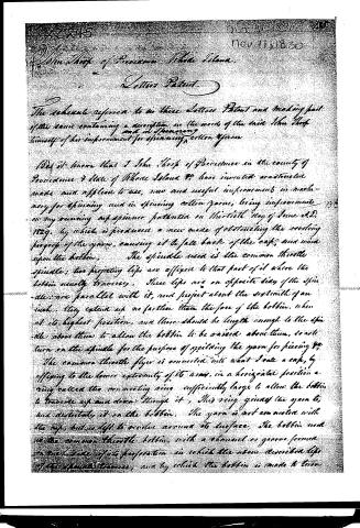
John Shep of Providence Rhode Island,
Letters Patent.
The subscriber refers to in these Letters Patent and making part of the same containing a description in the words of the said John Shep himself of his improvement for spinning cotton yarn.
Be it known that I John Shep of Providence in the county of Providence & State of Rhode Island &c have invented and invented made and applied to use, new and useful improvements in machinery for spinning and in spinning cotton yarn, being improvements on my own spinning machine patented on the twentieth day of June A.D. 1829, by which is produced a new mode of obstructing the winding proper of the yarn, causing it to fall back of the cap, and wind upon the bobbin. The spindle used is the common thistle spindle; two projecting lips are affixed to that part of it where the bobbin usually traverses. These lips are on opposite sides of the spindle; are parallel with it, and project about the septenth of an inch. They extend up no farther than the face of the bobbin, when at its highest position, and there should be length enough to the spindle above them to allow the bobbin to be raised above them, so as to turn on the spindle for the purpose of splicing the yarn for piecing &c. The common thistle flyer is converted into what I call a cap, by affixing to the lower extremity of its arm, in a horizontal position a ring entered the connecting ring sufficiently large to allow the bobbin to traverse up and down through it. This ring guides the yarn to, and distributes it on the bobbin. The yarn is not connected with the cap, but is left to revolve around its surface. The bobbin used is the common thistle bobbin, with a channel or groove formed on each side of its periphery in which the above described lips of the spindle traverse, and by which the bobbin is made to turn.
Page 3.
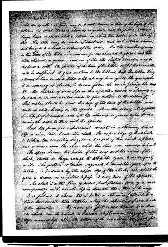
with the spindle; or there may be to each spindle, a tube of the height of the bobbin, in which the same channels or grooves may be formed, having a large head or collar at the bottom on which the bobbin will loosely sit. This tube may be made of sheet iron and not entirely closed, and braced to a head or collar of the same. In this case the opening in the side of the tube, will answer for one channel or groove, and the other channel or groove, and one of the lips on the spindle, may be suspended with the friction of the base of the bobbin on this head or collar will be sufficient to give motion to the bobbin, and the bobbin being allowed to turn on said tube, will at any time yield the yarn when it is necessary it should, be drawn from it, as in piecing the ends, &c. Or instead of said lips on the spindle, grooves or channels may be made in it, and a collar used to give motion to the bobbin. This collar should be about the size of the base of the bobbin and made to slide loosely on the spindle. From the side of its perforation two lips project inward, and into the channels or grooves in the spindle causing the collar to turn with the spindle.
But the principal improvement consists in a stationary spiral lip or rim, that I call the check. The upper edge of the check is within the connecting ring, one end, or part of this check is fixed, and remains above the rim, while the other end remains below it. The space between the inside of this ring and the outside of the check, should be large enough to allow the yarn to move freely in it. The friction or tension requisite to wind the yarn upon the bobbin, is produced by the upper edge of the check, over which the yarn is drawn or compelled to pass at every turn of the spindle. The check is a thin piece of metal, but flatwise forming a curve corresponding with a circle less in diameter than that of the ring. It is fastened to a bar or otherwise fastened to a fixed bar or rail that stretches along the spinning frame back of the spindle. By means of a flat or one turn on said bar the check can be raised or lowered at pleasure, causing its upper edge more or less above the bottom of the connecting ring and preventing
Page 4.
X6245
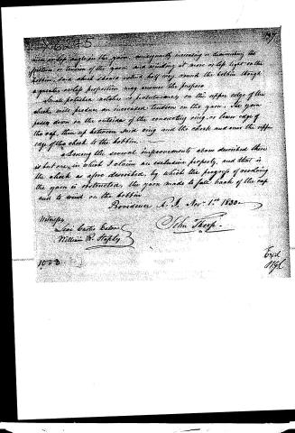
more or less angle in the yarn, consequently increasing or diminishing the friction or tension of the yarn, and winding it more or less tight on the bobbin, said check should extend half way around the bobbin though a greater or less proportion may answer the purpose.
Small polished notches or projections on the upper edge of the check, will produce an increased tension on the yarn. The yarn passes down on the outside of the connecting ring, or lower edge of the cap, then up between said ring and the check and over the upper edge of the check to the bobbin.
Among the several improvements above described there is but one in which I claim an exclusive property, and that is the check as afore described, by which the progress of winding the yarn is obstructed, the yarn made to fall back of the cap and to wind on the bobbin.
Providence R.I. Nov: 1st 1830
Witnesses
Levi Curtis Eaton
William W. Stapley
John Thorp
1070
Expt
Ngl
Published accounts: specification
Specification printed in the Journal of the Franklin Institute
Journal of the Franklin Institute, new ser., vol. 6 (1830), p. 388 · View the page
Text of the specification as printed in the Journal, from OCR; not proofread.
Specification of a patent for an improvement upon the Running Cap Spinner, which was patented on the 13th of June, 1829. Granted to JOHN THORP, Providence, Rhode Island, November 11, 1830. (WITH A COPPER-PLATE.) Be it known, that I, John Thorp, of Providence, in the county of Providence, and state of Rhode Island, &c. have invented, constructed, made, and applied to use, new and useful improvements in machinery for spinning, and in spinning cotton yarns, being improvements on my running cap spinner, patented on the 13th day of June, A. D. 1829, by which is produced a new mode of obstructing the revolving progress of the yarn, causing it to fall back of the cap, and wind upon the bobbin. The spindle used is the common throstle spindle. Two projecting lips are affixed to that part of it where the bobbin usually traverses. These lips are on opposite sides of the spindle, are parallel with it, and project about the sixteenth of an inch. They extend up no further than the base of the bobbin, when at its highest position, and there should be length enough to the spindle above them, to allow the bobbin to be raised above them, so as to turn on the spindle for the purpose of yielding the yarn for piecing, &c. The common throstle flyer is converted into what I call a cap, by affixing to the lower extremity of its arms, in a horizontal position, a ring called the connecting ring, sufficiently large to allow the bobbin to traverse up and down through it. This ring guides the yarn to, and distributes it on, the bobbin. The yarn is not connected with the cap, but is left to revolve around its surface. The bobbin used, is the common throstle bobbin, with a channel, or groove, formed on each side of its perforation, in which the above described lips of the spindle traverse, and by which the bobbin is made to turn with the spindle. Or, there may be to each spindle, a tube of the length of the bobbin, in which the said channels, or grooves, may be formed, having a large head, or collar, at the bottom, on which the bobbin will loosely set. This tube may be made of sheet iron, and not entirely closed, and brazed to a head, or collar, of the same. In this case, the opening in the side of the tube, will answer for one channel, or groove, and the other channel, or groove, and one of the lips on the spindle may be dispensed with. The friction of the base of the bobbin on this head, or collar, will be sufficient to give motion to the bobbin; and the bobbin being allowed to turn on said tube, will at any time yield the yarn when it is necessary that it should be drawn from it, as in piecing the ends, &c. Or, instead of said lips, on the spindle, grooves, or channels, may be made in it, and a collar used to give motion notion to the bobbin. This collar should be about the size of the base of the bobbin, and made to slide loosely on the spindle. From the sides of its perforation, two lips project inward, and into the channels, or grooves, in the spindle, causing the collar to turn with the spindle. But the principal improvement consists in a stationary spiral lip, or rim, that I call the check. The upper edge of the check is within the connecting ring. One end, or part of this check, is placed and remains above this ring, while the other end remains below it. The space between the inside of this ring and the outside of the check, should be large enough to allow the yarn to revolve freely in it. The friction, or tension, requisite to wind the yarn upon the bobbin, is produced by the upper edge of the check over which the yarn is drawn, or compelled to pass at every turn of the spindle. The check is a thin piece of metal, bent flatwise, forming a curve corresponding with a circle less in diameter than that of the ring. It is fastened to a knee that is bolted, or otherwise fastened, to a fixed bar, or rail, that stretches along the spinning frame, back of the spindle. By means of a slot, or mortise, in said knee, the check can be raised or lowered at pleasure, carrying its upper edge more or less above the bottom of the connecting ring, and producing more or less angle in the yarn; consequently, increasing or diminishing the friction, or tension of the yarn, and winding it more or less tight on the bobbin. Said check should extend half way round the bobbin, though a greater or less proportion may answer the purpose. Small polished notches, or protuberances, on the upper edge of the check, will produce an increased tension on the yarn. The yarn passes down on the outside of the connecting ring, or lower edge of the cap, then up between said ring and the check, and over the upper edge of the check to the bobbin. Among the several improvements above described, there is but one in which I claim an exclusive property, and that is, the check, as above described, by which the progress of the revolving yarn is obstructed, the yarn made to fall back of the cap, and to wind on the bobbin. JOHN THORP. References to the Plate of J. Thorp's improved Running Cap Spinner. A, the spindle. B, the cap. C, the connecting ring. D, the box that forms the upper bearing E, the step in which the spindle stands. F, the bobbin. of the spindle. G, the head or collar on which the bobbin stands. H, the tube on which the bobbin loosely turns. I, I, the check, that obstructs the revolving progress of the yarn, causing it to fall back of the cap, and wind on upon the bobbin. J, J, two lips on the spindle, formed by soldering two pieces of wire to it. They slide in the two channels formed in the bobbin or tube, causing the bobbin to turn with the spindle. K, the whirl. L, a collar that slides loosely on the spindle. From its perforation two lips project inward, and into the channels in the spindle, by which the collar is made to turn with the spindle. The bobbin sets on this collar, and the friction of its base on the collar gives motion to the bobbin. This collar, as well as the head or collar of the tube, H, sets on the vibrating rail or lifter of the common throstle frame, and moves with it to distribute the yarn on the bobbin. M, M, one of the channels or grooves in the spindle. The other is directly opposite to it. In altering spinning frames now in use, or those where the spindles are small, it would be better to use the lips, rather than the channels, as the latter would weaken them. In building new spinning frames, the spindles can be made enough larger for that purpose. They both work equally well. The yarn is represented as passing through the loop above the spindle. Fig. 3, represents the check. This will answer a good purpose in making cotton roving, &c.
Published accounts: journal notice
Notice in the monthly list of patents, with remarks
Journal of the Franklin Institute, new ser., vol. 7 (1831), p. 165 · View the page
37. For an improvement in Spinning Cotton Yarn, &c. being improvements in his running cap spinner, &c.; John Thorp, Providence, Rhode Island, November 11.
Remarks. The specification of this patent was published in our last volume, page 288.
About this record
- Patentee
- the Journal of the Franklin Institute, Journal
- Date
- the Name and Date index of patents, USPTO records, Jim Shaw's X-patent list
- Invention
- the Name and Date index of patents
- Listed in
- the Name and Date index of patents, USPTO records, Jim Shaw's X-patent list, the Journal of the Franklin Institute, Burke's List of Patents (1847)
- The patentee's full name comes from the Franklin Institute's journal.
- Burke's 1847 Patent Office list gives the same patent.