

Drawings and documents
National Archives restored drawings: drawing
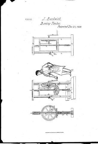
Jedediah Beckwith's Patent Drawing for a Machine for Boring Timber

National Archives, Restored Patent Drawings (Record Group 241) · Full-size scan at the National Archives · Catalog record
Show the text on the drawing Hide (39 words)
Words on the drawing as machine-read by the National Archives; not checked. Useful mainly for searching.
143g WOOD WORKING. / Portable / 2. GENERAL WORK MACHINES. DORING pooM 'DM / JEDEDIAH BECKWITH / Vec. 21/30 / [173] Boring. / $2- / Boring Timber. / Patented December 21° 1830. / 6301.X / LIVISION. / Oli / Section
USPTO scan
The patent as scanned by the USPTO
-
 Page 1
-
 Page 2
-
 Page 3


U.S. Patent and Trademark Office · Google Patents
Show the transcription Hide (478 words)
Machine transcription (LightOnOCR) of the pages as scanned by the USPTO, most of them the handwritten copies made when the records were restored after the 1836 fire. Not checked; it can misread handwriting, so compare it with the scan.
Page 1.
6301X
J. Beckwith,
Boring Timber.
Patented Dec. 21, 1830.
AM. PHOTO-LITHO. CO. N.Y. (OSBORNE'S PROCESS)
Page 2.
X6301 Dec 21 1850 407
Jedediah Beekwith
Letters Patent
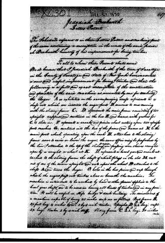
The Schedule referred to in these Letters Patent and making part of the same containing a description in the words of the said Jedediah Beekwith himself of his improvement for boring timber.
To all to whom these Presents shall come
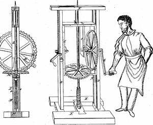
Be it known that I Jedediah Beekwith of the town of Saratoga in the County of Saratoga and State of New York have invented a new and useful improvement for boring timber and that the following is a full and exact description of the construction and operation of the said machine as invented by me for working the Auger A as exhibited on the accompanying draft represents a shaft into which are inserted the auger points B, secured to and moving with the sliding frame C. D. represents the main frame consisting of two uprights capped and mortised in the box B, and braced with grooves for C, to slide on. E. represents a crank and pinion wheel resting upon two upright posts marked G, mortised into the box of the frame and braces at N, to the main post which operating upon the rack H, attached to the sliding frame serve to raise or lower the auger, the same office may be performed by the line I attached to the top of the sliding frame passing over sheaves wrought upon by a weight or wheel at K. L, represents a bevel gear and crank attached to the sliding frame the shaft of which plays in the slot M, cut out of one of the main uprights and acts upon the wheel P, attached to the shaft A and turns the auger. O, holes in the box piece and cap through which the auger passes into timber above or beneath the machine. The machine is intended to be worked by hand or other power applied to the bevel gear shaft and to be used in boring all kinds of timber and in any position. It will be useful in ships, bridges and coach building. The dimensions of a machine capable of boring 25 inches deep are as follows. Box frame B, 3½ feet long 4 inches broad 3 by 4 inch timber. Uprights D, 4½ long, cap 2½ long timber 3 by 4 inch stuff. Sliding frame C, 2.5 long 20 inches
Jedediah Beekwith
Page 3.
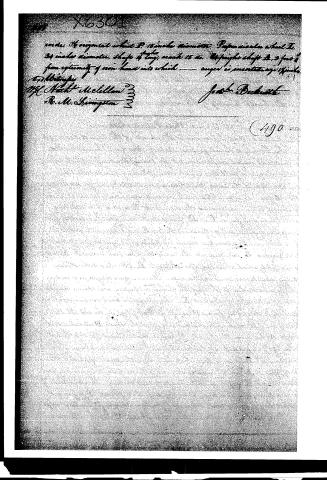
order. Horizontal wheel P, 15 inches diameter. Perpendicular wheel H, 24 inches diameter. Shaft of tang, 15 inches. The straight shaft is 3 feet 6 inches from extremity of iron head into which — angle is inserted, 15 inches.
By Authority
H. H. Hatch McCallan
R. M. Livingston
Jacob Breckinridge
(190)
Published accounts: journal notice
Notice in the monthly list of patents, with remarks
Journal of the Franklin Institute, new ser., vol. 7 (1831), p. 251 · View the page
36. For an improvement in the art of Boring Timber; Frederick Beckwith, Saratoga, Saratoga county, New York, December 21.
Remarks. A frame is made, having two uprights, or cheeks, like those of a standing press. Within this there is a sliding frame, passing freely up and down. A cylindrical vertical shaft fits and turns freely in holes at the top and bottom of the sliding frame; the augers, or bits, with which the boring is to be performed, are adapted to the lower end of the shaft. By means of a crank, or handle, motion is given to a vertical wheel, the cogs of which take into those of a horizontal wheel upon the shaft. The machine is intended to be used in ship, bridge, and dock building, and for other purposes. We are not informed what part is claimed, and it resembles other machines for the same purpose so closely, that we should be at a loss in designating what is new in it.
DATAMP: illustration
Illustrations from DATAMP

DATAMP (Directory of American Tool and Machinery Patents), via the Internet Archive · Archived DATAMP page
About this record
- Patentee
- DATAMP
- Date
- the Name and Date index of patents, DATAMP, USPTO records
- Invention
- DATAMP
- Listed in
- the Name and Date index of patents, DATAMP, USPTO records, Jim Shaw's X-patent list, the Journal of the Franklin Institute, Burke's List of Patents (1847)
- Burke's 1847 Patent Office list gives the same patent.