

Drawings and documents
National Archives restored drawings: drawing
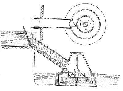
W. Kendall's Patent Drawing for a Method of Applying Water to Mill Wheels

National Archives, Restored Patent Drawings (Record Group 241) · Full-size scan at the National Archives · Catalog record
Show the text on the drawing Hide (79 words)
Words on the drawing as machine-read by the National Archives; not checked. Useful mainly for searching.
188. HYDRAUL 10 MOT / Vol.12 hage 283 / 13 / Tarbins, / Ton & Side Direct Supply. / CLASSIFICA TION / 6336.X / W O KENDALL / DIV ISION. / Applying water toMill wheels / Patented 12th Ian 183/- / Secrion / A. Draught of Wheel / B. Platform / G. Shaft / D.Wheel D / E. Penstock / c/ / Poliat office Nov 30 1841 / Made under the direction of the Comminous / of Patents neith ach of 3 Morch 1837 / Strickland Del / ML Eumorth / Commissions Palemb
USPTO scan
The patent as scanned by the USPTO
-
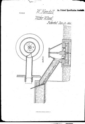 Page 1
-
 Page 2
-
 Page 3
-
 Page 4
-
 Page 5
-
 Page 6
-
 Page 7
-
 Page 8
-
 Page 9
-
 Page 10
-
 Page 11
-
 Page 12


U.S. Patent and Trademark Office · Google Patents
Show the transcription Hide (4,072 words)
Machine transcription (LightOnOCR) of the pages as scanned by the USPTO, most of them the handwritten copies made when the records were restored after the 1836 fire. Not checked; it can misread handwriting, so compare it with the scan.
Page 1.
6336X
W. Kendall,
Water Wheel,
Patented Jan. 12, 1831.
No Printed Specification Available
Page 2.
Jan 12 1881
William Kendall, Fairfield, Mass.
Letters Patent. X 6336
The sheets referred to in these Letters Patent, and making part of the same, containing a description in the words of the said William Kendall himself of his improvement in the mode of applying water to Mill wheels.
To all persons to whom these presents shall come, William Kendall of Fairfield in the County of Somerset and State of Maine, Millerwright, sends greeting. Be it known that William Kendall, have made a new and useful discovery or invention in the application of water whilst acting upon Mill wheels which he calls the Syphon principle, that is after the water has performed the full measure of its first action upon the wheel by percussion, or rather by reaction, the water in passing the wheel has been required a velocity equal to that from a gate under the same head; the effects of this velocity of the water is still continued by this invention to act upon the same wheel by causing its force to be expended in removing the atmosphere, vacuum from the lower or opposite side of the oblique buckets and openings of the wheel, which pressure never exceeds, yet always is equal to the weight or head of water of 33 1/3 feet, or fifteen pounds to the square inch; this pressure becomes proportionally diminished according to the head of water used; by causing the water from the wheel to pass off, between two plain surfaces, with a fixed space, of proper degree larger than this body of water in motion naturally occupy, this space becoming an increased air it extends from the wheel, and does not remain to be extended farther than to allow its extended measure of opening to be sufficient to discharge the quantity of water expended by the wheel at the rate of from ten to six feet per second as the variety of water may require; this discharge in all cases must be laid below the surface of the water that the air may be prevented from entering within, this is all the draught of the wheel.
Page 3.
wheel it not so a syphon and will be better explained after explaining the common art or science as it stands at the present time. In shot wheels or water acting by its gravity they have the advantage of producing effects greater and greater, as we enlarge the wheel for holding & retaining all the water until its motion becomes scarcely discernable, yet it is not in our power to obtain one third more in effects from them, than is obtained by following the judicious rules, directed by clever brains how their effects are estimated at two thirds of the power applied, the requisite strength and expense is proportionally increased, if we rise beyond this diminishing one we increase the other in the same geometrical progression.
The next case is where one half the velocity is multiplied by three quarters of its greatest force, as water acting by percussion on undershot wheels which are variously made, and in these most perfect from their effects are rated at 7/8 of the power applied. Here form an application of your invention, by using thin buckets of about one third the width of the acting column of water, and increasing the number in that ratio their effect becomes increased; a suggestion of this principle as applicable to steam boat wheels was published in 1808, intending for that purpose it should be given the advantage in propulsion at the back side of the buckets. But here I specify that from a reaction force, not only from reaction that may arise from a weight of water blow the wheel by placing it near the upper part of a confined space, but from velocity or its force of percussion then applied, by my invention which claims. Reaction wheels are those wheels more by reaction of the water, their effects have been estimated by the same ratio as undershot wheels; this principle of reaction of fluids was first noticed in Roman time, but only from one of their mills suspended having an oblique in use the rotary motion & notion was given. At the late Dr. Bache applied it to mechanical purposes, from an issue at the end of a hollow arm, and after this applied to a circular wheel to act under water by having many a barge of it. By this the whole head can be used and many advantages for mills obtained where no other wheel could be applied, yet this apparent
Page 4.
valuable principle asserted only by a very wholesale abridgement in the late edition of this work alleging that they (the wheels) have not discovered the copulations intended of him. This was reasonable and owing to the want of a proper system to construct the wheels they have generally made a much waste of water in a short time after built as their use required, much of this was by reason of the difficulty in connecting the main rim to the shaft, this with the changing position from the wearing of the quagon, the unwhipping of the wheel in other parts, causing its wearing rims near away the space between it and the steam, making water waste by every particle that is drawn within by the water, I have this part to construct with in wheels of my construction, but the assurance that the wheel will support a perfect circle and that this shining is smaller and in that part where the velocity of the water is great and in every direction to make waste or retain the particles to cause its wearing away.
From all reaction wheels the quantity of water which issues from the wheel is increased with the velocity of the wheel, and also the velocity of the water is increased when the motion of the wheel is diminished by it and.
From inventor presumes that he will be secured from making a more particular investigation, by saying that in 1816, he gave his common reaction wheel to present form of buckets by making them thin of wood and iron, instead of special experiments, this was an improvement as there was no stop action of resistance against the backside of the buckets, they being only caused, sufficient to give a propulsion to the discharging water shortly after; this became under a patent from a person unknown to me, and I presume never explained the principle, neither hath it ever been explained with repeating him, they discharge the water outward from the shaft the buckets were between two rims, with the shaft connected to one, but the wheel which I have constructed and applied to my invention have buckets so set more at right angles with the former which are
Page 5.
X 6334
lie thus. The water may seem to act upon it by pressure from the side of the head, but it is only by reaction that the wheel moves.
This wheel which I have constructed for ease in making and permanency of its parts may be present at a glancing view, that which was formerly called a tub wheel except it has no arms, the buckets entering the shaft are supported in the rim, they lie very flat and very thin, their edges which cut and have the water, are made sharp by their obliquity. They so as to lay one each other, and the space between them all is called the sheath, or opening of the wheel, they decline about three or four inches to a foot of their width, for a wheel of some feet diameter with seven buckets their width becomes about 15 inches at the shaft and two feet at the rim; this rim then requires to be about ten inches and 1/2 deep so as to extend one inch below the buckets, and two inches above the piping a feather edge bar of iron through with its thick edge resting against, and fair with the buckets on a cutter one end being drawn well into the shaft the other end bent down and supported under a hoop which binds the rim and wheel, which has an concave form at its upper side, and is nearly flat at its bottom, it has a shaft for its support commonly of half the diameter of the wheel, whose mortices are made small portions of the wheel are left to support its short end, the buckets being slit to fit the same, if the buckets were wholly of iron, plate or cast iron made smooth it would be better, although as it is requisite that the wheel should be always under water, it is not subject to decay still for high heads, the wheels should be made wholly of metal, with just proportion fair & smooth, as they become very small, hence after one of such wheels will be devised. The next is the gudgeon; so much difficulty has attended this point in the common reaction wheel as to render one objection to their use, and although the wheels of my construction, have less weight from their reduced size, still an improvement in the way is most urgent, and that the wheel may be raised or lowered adjusting it for the height by the same. Therefore gudgeons for the wheels are made of wood and to be easily managed above the wheel.
Page 6.
it is made of any convenient length, say six feet and from four to six inches square, without weight required. This stands in the shaft with a thin tapering piece at two of its sides for its support; it is also supported by being blocked down at one of its corners, the weight causing it to cramp; so that it never alters, its lower end at its sides rests against a perfect square hoop made of plate iron, and two inches wide, which is headed, and secured in the shaft, as a bushing. The thin ends of the above tapering pieces, entering them for convenience on the nearest and right side, with the said blocking on the same corner; a view of the gudgeon standing in an open mortise above the wheel. This mortise is not obliquely and so large as to withdraw the gudgeon readily after the weight of the shaft is removed from the said blocking, and for its security in moving commonly on greater part of the wood is proportionally more firm in its centre, and more autumn. The hoop for this gudgeon to wear upon is commonly cast iron about one and a inch thick with a projecting edge to rest upon the wood, which is a floor or rather a platform, made somewhat conical, and extends beyond the rim of the wheel forming the lower part of the trough; the centre of this platform is filled for the brim as it hangs upon its edge, clear water surrounds its bottom, and its bottom sink hole is made at one side of the centre of the box, and the wood is excepted away from its bottom, with a large hole continued down through, that the water may rise for the moving part it has circular concaves of the proportion of half an inch deep for five inches face. This is called a tremulous motion when necessary to inhale the water between the surfaces. This system will not wholly apply unless for upright shafts and for wheels over two feet in diameter, referring to common pictures for gudgeons when otherwise, and to observe the above principle, continuing to describe the wheel and pictures for applying Leupholon principle. The wheel is not supposed to stand upon its for three with the lower part of its inner for above the platform as to give an opening between them equal to twice that of the opening of the wheel (this may vary in some cases).
Page 7.
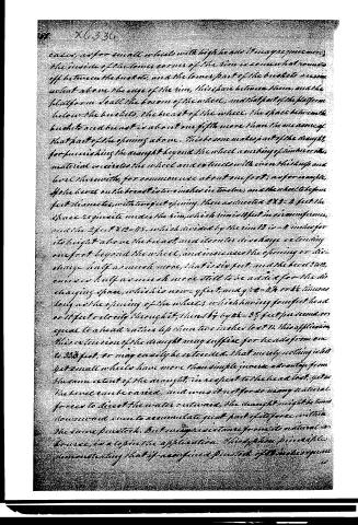
cases, as for small wheels with high heads and large peripheries, the inside of the lower corner of the rim is somewhat rounded off between the buckets, and the lower part of the buckets are somewhat above the edge of the rim, this space between them and the platform seals the bottom of the wheel, and that part of the platform below the buckets, the breast of the wheel. The space between the buckets and breast is about one fifth more than the measure of that part of the opening above. This is some makes part of the draught, for furnishing the draught beyond the wheel a washing of water or the material circulates the wheel and extends with even thickness and level therewith, for common use about one foot, as for example, if the head on the breast is two inches in twelve, and the wheel to be ten feet diameter, with two feet opening. Then as directed 2 x 2 = 4 feet the space to be inside under the rim, which rim is 18 feet in circumference, and the 4 feet 4 x 12 = 48, which divided by the rim 12 in = 4 inches for its height above the breast, and it will discharge extending one foot beyond the wheel, and increases the opening or discharge half as much more, that is six feet, and the head 3 in, or one and half as much more still to be added for the discharging space, which is now 9 feet, and 9 x 2 = 18 or 18 times as long as the opening of the wheel, which having four feet head or 18 feet is clearly through it, then 18 by 6 x 2 = 35 feet per second or equal to a head rather less than two inches lost. In this application, this extension of the draught may suffice for heads from one to 30 feet, or may easily be extended. That merely nothing is lost yet small wheels have more than simple increase advantage from the same extent of the draught, in respect to the head lost, yet as the head can be varied, and was it not for so many natural forces to direct the water outwards, the draught might be time downward even to accumulate great part of its force within the same periphery. But every resistance from its natural course, is a loss in the application. This is from principle demonstrating that if no confined point out of the wheel is given
Page 8.
is fitted under a head of water of 33 1/3 feet and moves below the surface its gate then having the pressure 20 5/8 lbs when shut, and if the gate is half opened it will then have the same pressure on the half gate, that it had on the whole surface, whilst it was shut for when the gate is half down the succession of the issuing water repels the incumbent water from the lower side and produces a vacuum there, and if this half gate is allowed to move onward through the penstock, with half the natural velocity of the water (or 1/3 feet per second) which is the same velocity which is given by 1/2 of the head 33 1/3 ft = 16 5/8 that is 16 5/8 feet, it would then have the pressure exerted upon it, equal to 3/4 of that which it had before it moved, which is 15 of 20 5/8 lbs or 15 1/2 lbs, moving this with half the velocity of the water, whilst the opening removed is but the half of 20 5/8 or 10 4/8 lbs, and if this gate was laid inclining to represent the brake of the wheel, on which I apply this principle with the same effect, the above may suffice to show the reason why the wheel requires double resistance to stop its motion, than the whole amount of pressure removed by its openings, that is one half of the opening for the wheel, with this application produces equal effects to, that which was established for the common reaction wheel, or with the same opening, produces double effect, or hereafter explained, the water acts upon the wheel by its whole head, & whatever may be its velocity in directing it into the stream (on revolving the wheel) its motion should be the same, way which the wheel may move, as from the opening being directed to that side of the shaft to give this motion round the shaft, and if the wheel is within a penstock where the water ascends to its high fixtures etc. spirally should be affixed to its sides to give the direction, this securely prevents a whirl pool which would otherwise destroy the action, and also have other proper effects for preventing waste of water outside of the rim and a permanent diffusion is placed upon the curbing timber and
Page 9.
and covering the side of the wheel its innermost edge adjoining therewith, and having thin warped wood nailed so as to extend down to touch the rollers or buckets. The wheel is supposed to be turned of by its motion in that part. The wheel should have a small diameter merely sufficient to admit the requisite quantity of water. There is assurance that its inner surface and weight with increased velocity at its continuing, all tend to diminish friction, and the water acting upon it with great force, yet as we increase its size the buckets become more flat for convenience, having one wheel of proper form, the diameter of another, with different openings, may be found from the square of the diameter of the given wheel more or less as the proportion of their openings may be the square root of the product is the diameter of the required wheel, to apply different powers with different heads; the quantity of water or rather the power to be used, must be estimated by common power, such as that of a millstone of four feet diameter, requiring 200 lbs to be constantly exerted at a point two feet from its centre where the velocity is 27 feet per second, then 200 x 27 is 5400 or 2000 lbs is raised one foot per second by that power, and for two pounds it would be 2000 lbs, one foot high per sec. and the weight of one cubic foot of water is 62 lbs, which x by the whole head in feet gives the pressure on one foot of surface, or opening removed, and from this foot, more or less, as the opening of the wheel may be, to which add half as much more for the maximum load. This being multiplied by half the velocity of the water per second in feet, gives the effect, and in the comparison of the above the velocity of the water per second divided by 8 gives the square root of its head & the square root of its head x 8 is its velocity per second in feet. Then if the wheel had a foot head applied with 2 feet opening its effect would be stated as follows 2 x 8 x 2 = 32, and 2 x 8 x 2 by 2, the opening, the product is 128 or 2 1/2 millstones, and its centre of action being
Page 10.
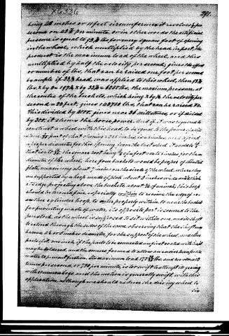
being 48 inches or 4 feet circumference it revolves 8 per second or 480 per minute, or in other words the artificial pressure is equal to 95 3/4 lbs for every square foot of opening in the wheel, which multiplied by the head in feet, the product is the maximum load of the wheel, and this multiplied by half the velocity per second, gives the lbs or number of lbs, that can be raised one foot per second.
Example: If 33 1/3 head, was applied to this wheel, then 95 3/4 lbs. x by 2 = 197 1/2 x by 33 1/3 = 6585 lbs, the maximum pressure, at the centre of the buckets, which being x by 1/2 the velocity per second = 24 feet, gives 118750 lbs, that can be raised.
This divided by 8877, gives near 36 millistones, or if divided by 330, it shows the horse power. And if it was required to construct a wheel with this head, to be equal to the power of one stone, 1/3 part of that opening = 255 inches, i.e. 21 inches, must be fixed a proper diameter for this opening from the last wheel. It would be 1/4 times = to 5/8, the square root being 1/2 of a foot or 6 to 5 inches for the diameter of the wheel, here four buckets would be proper of similar plate, measuring about 7 inches on the circle of the wheel, where they are supported by a hoop made of plate about 2 inches wide and 1/4 thick, its edge projecting above the buckets, about 1/4 of an inch; this hoop should be turned fair, especially within to receive the edge of an another cylindrical hoop, to enter properly within, to near the buckets for preventing waste of water, its opposite part is secured to the forestock, as the wheel is supposed to sit within one, and its shaft to extend through the sides of the same, observing that the shaft may become 2 1/2 or 3 inches diameter, for the support of the wheel, and the parts of it, one inch, if the joints to be connected are first sealed with oil may be believed, and the corners formed to allow an easier turn for the water to prevent friction. Its maximum load 173 3/4 lbs. and revolves 12 times per second, or 720 per minute, is too swift to attempt its gearing with common begs, and the motion is generally swift, with this application, although we should reduce the driving wheel to
Page 11.
X6336
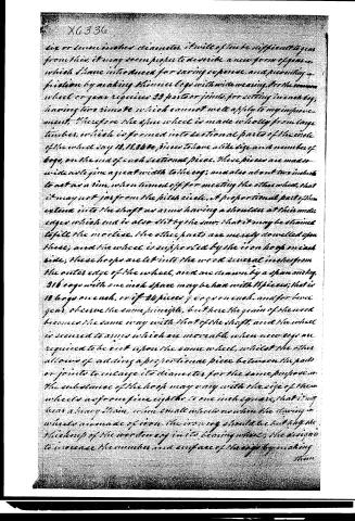
six or seven inches diameter, it will often be difficult to get from this, it may seem proper to describe a new form of gear, which I have introduced for saving expense, and preventing friction by making the inner cogs with wide wearing. For the common wheel or gear requires 23 parts or joints, for setting in each bay, having two rims to which cannot well apply to my improvement. Therefore the outer wheel is made wholly from large timbers, which is formed into sectional parts of the circle of the wheel say 12, 15, 24 &c, pieces to have a like size and number of cogs, on the out of each sectional piece. These pieces are made wide as to give a great width to the cog; and also about two inches to act as a rim, when turned off for meeting the other wheel, that it may not jar from the pitch circle. A proportional part of them extend into the shaft as arms having a shoulder at their under edges which end is also slit by the saw, that it may be strained to fill the mortice. The other parts are merely dowelled upon these; and the wheel is supported by the iron hoops on each side; these hoops are let into the wood several inches from the outer edge of the wheel, and are drawn by a span and key. 216 cogs with one inch space may be had with 15 pieces; that is 12 cogs on each, or if 24 pieces 7 cogs on each. And for lower gear, observe the same principle, but here the gear of the wood becomes the same way with that of the shaft, and the wheel is secured to arms which are movable when new cogs are required to be cut upon the same wheel, whilst the other allows of setting a proportional piece between the parts or joints to enlarge its diameter for the same purpose. The substance of the hoops may vary with the size of the wheels as from five eighths to one inch square, that it may bear a heavy strain, when small wheels as when the driving wheels are made of iron. The iron cog should be but half the thickness of the wooden cog in its bearing wheel; the design to increase the number and surface of the cogs by making them
Page 12.
X6336
292
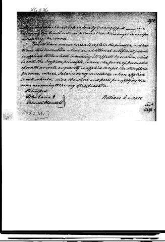
under and shorter which is done by turning off no — and allowing the steam to a space between them & the auger is made for removing the wood.
I have made an effort to explain the principles, and how to use this invention where an additional artificial pressure is applied to the wheel increasing its effects by suction; which I call the Suction principle, where the force of percussion of water as well as gravity is applied to repel the atmospheric pressure, which I claim in my invention, when applied to mill wheels; also the wheel and parts for applying the same according to this my specification.
Witnesses
John Davis 2
Samuel Maindell 3
William Kendall
2052
2052
Published accounts: journal notice
Notice in the monthly list of patents, with remarks
Journal of the Franklin Institute, new ser., vol. 7 (1831), p. 306 · View the page
21. For the Application of Water to Mill Wheels; which the inventor calls "the Syphon Principle, or Artificial Pressure;" William Kendall, Fairfield, Somerset county, Maine, January 12.
Remarks. The specification of this patent is drawn up with great labour; it includes many numerical calculations, and an essay upon the application of water in mills of different kinds. From the course pursued it would be extremely difficult to give an analysis or epitome of this paper; we will, however, make one or two quotations, which may perhaps afford a general idea of the proposed plan. The wheel is a kind of tub wheel, with the buckets secured between two rims, with the shaft connected to one of them. "The wheels which I have constructed and applied to my invention, have buckets, as it were, at right angles with the former wheels, and lie thus \\\. The water may seem to act upon it by pressure from the whole of the head, but it is only by reaction that the wheel moves. This wheel which I have constructed for ease in making, and permanency of its parts, may represent at a glancing view, that which was formerly called a tub wheel, except it has no arms, the buckets entering the shaft, and are supported in the rim; they are very flat, and very thin; their edges which cut and leave the water are made sharp. By their obliquity they scarp or lap over each other, and the space between them all is called the throat, or opening of the wheel; they decline about three or four inches to a foot of their width. For a wheel of four feet diameter, with seven buckets, their width becomes about fifteen inches at the shaft, and two feet at the rim. This rim then requires to be about ten and a half inches deep, so as to extend one inch below the buckets, and two inches above, for passing a feather edged bar of iron through with its thick edge resting against, and fair with, the buckets, as a cutter; ⚫ one end being driven well into the shaft, the other end bent down and supported under a hoop, which binds the rim and wheel," &c. The specification, of which we have copied a very minute part, thus concludes: "Thus have I endeavoured to explain the principles and how to use this invention, where an additional artificial pressure is applied to the wheel, increasing its effects by suction, which I call the syphon principle, where the force of the percussion of water, as well as gravity, is applied to repel the atmospheric pressure, which I claim as my invention when applied to mill wheels. Also the American Patents for January, with Remarks. wheel and parts for applying the same according to this my specification." We confess that we do not understand the reference to the atmospheric pressure, and the syphon principle, although we have carefully read the parts in which they are described; but the description is an involved one, and we could not take the time to make it a study, without a fair prospect of learning something from it. The drawing which accompanies the specification, lends little or no aid to the description, being very indifferently executed.
DATAMP: illustration
Illustrations from DATAMP

DATAMP (Directory of American Tool and Machinery Patents), via the Internet Archive · Archived DATAMP page
About this record
- Patentee
- DATAMP
- Date
- the Name and Date index of patents, DATAMP, USPTO records
- Invention
- DATAMP
- Listed in
- the Name and Date index of patents, DATAMP, USPTO records, Jim Shaw's X-patent list, the Journal of the Franklin Institute, Burke's List of Patents (1847)
- Burke's 1847 Patent Office list gives the same patent.