

Drawings and documents
National Archives restored drawings: drawing
Jonathan Newhall's Patent Drawing for a Planing Machine

National Archives, Restored Patent Drawings (Record Group 241) · Full-size scan at the National Archives · Catalog record
Show the text on the drawing Hide (103 words)
Words on the drawing as machine-read by the National Archives; not checked. Useful mainly for searching.
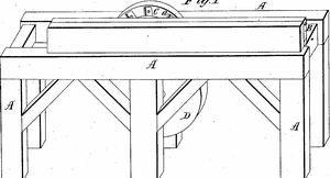
144. WOOD WORKING MACHINES. / Planers, Rotary Disk. / $150 / Jonathan Newhall / Vol.13.p.g7.. / CLASSIFICATION / Planing Machine Sumber / 6350-X / Patented 25th JanM. 1831, / DIVISION. / Fig.1, / Fight / 60 / Fig.2. / Newhall pany. 25. 25.1831, / Cc / References. / Fid.1. planing machine. Fig.2. end view. Fid 3 plane- / wheel detatched enlarged view. / Patent Afui Dee 9.th/841 / A. frame, B,carriad. C.plane wheel D. drum. / C Made under the direction of the Commission of Patents / Ensliding box. F. screw. a, bevelon wheel. b.plane irons. / C, metalic plates. / in couf onity with act of Congrep 3 March 1834 / L Sumorth of Patents
USPTO scan
The patent as scanned by the USPTO
-
 Page 1
-
 Page 2
-
 Page 3


U.S. Patent and Trademark Office · Google Patents
Show the transcription Hide (803 words)
Machine transcription (LightOnOCR) of the pages as scanned by the USPTO, most of them the handwritten copies made when the records were restored after the 1836 fire. Not checked; it can misread handwriting, so compare it with the scan.
Page 1.
6350X
J. Newhall,
Wood Planing Machine.
Patented Jan. 25, 1831.
Fig. 3
Fig. 1
Fig. 2
AM. PHOTO-LITHO. CO. N.Y. (OSBORNE'S PROCESS)
Page 2.
6350X
Jan. 25, 1831
97
Jonathan Newhall
Letters Patent.
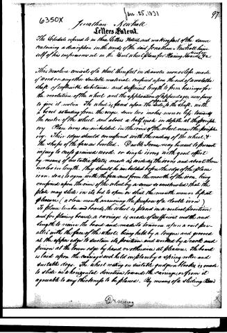
The Schedule referred to in these Letters Patent and making part of the same containing a description in the words of the said Jonathan Newhall himself of his improvement in the level wheel plane for planing boards, timber, etc.
This machine consists of a wheel three feet in diameter, more or less, made of wood or any other suitable material, confined upon the end of a metallic shaft of inflexible substance and sufficient length to form bearings for the revolution of the wheel and the application of a pendulum, necessary to give it motion. The wheel is fixed upon the side of the shaft, with a level extending from the verge, some two inches more or less, towards the centre of the wheel, and about a half inch in depth at the periphery. Plane irons are pinbedded in the rim of the wheel near the periphery. Their edges should correspond with the radius of the wheel, and the shape of the face as bevelled. Double irons may be used to prevent injury to coarse grained wood, or single irons with good effect by means of metallic plates, made as wide as the irons and about three inches in length. They should be imbedded before the edge of the plane iron, so as to agree with the face and form the mouth of the iron, being confined upon the rim of the wheel by a screw so constructed that the plate may slide in its bed to open or shut the mouth more or less at pleasure. (a close mouth answering the purpose of a double iron)
To plane timber and boards, the wheel is placed in a vertical position, and for planing boards, a carriage is made of sufficient width and length to receive the board and made to traverse upon a rail parallel with the face of the wheel, being held by a tongue and groove at the upper edge to sustain its position, and worked by a rack and pinion at the lower edge by hand or otherwise at pleasure. The board is laid upon the carriage and held in place by a spring roller and suitable dogs. The wheel resting on suitable guides or blocks is made to slide in a horizontal direction towards the carriage, or from it agreeable to any thickness to be planed. By means of a sliding bar
Dr. A. W.
Page 3.
98 6350x Jan 25, 1831
filled to the shaft so as to carry the wheel along with it. A lever or screw is attached to the Box, and thereby brought to bear on the wheel, to give it the position required. To plane joint a carriage is made of timber of suitable length, thickness, and width to receive the joint which is laid upon it with the side to be planed projecting towards the wheel over the edge of the carriage as much as is to be planed off, and held down by dogs at each end of the same formed for the purpose. The carriage for joint and timber should run on two rails near its under edges, and may be worked by a rack and pinion or otherwise at pleasure. A horizontal position of the wheel is recommended when boards or planks only are to be planed. The frame may be made according to circumstances, and any convenient power may be applied. The principles which I claim as new and being my invention are:
1st The Boxel on the face of the wheel, the use of which is to admit the lumber to enter between the carriage and the verge of the wheel and thereby presenting the part to be planed off to the action of the planes.
2nd The sliding motion of the wheel, by which various thicknesses may be planed.
3rd The running the lumber by the centre as in the above description of planing boards.
4th The metallic plates, the use of which is to answer the purpose of double irons, which principle is contemplated to be applied to hand planes.
In testimony that the foregoing is a true specification of the invention herein described and of the mode of using the same I have hereunto set my hand and seal at Washington in the County of Lincoln and State of Maine this fourth day of January in the year of our Lord one thousand Eight hundred and thirty one.
Witneses
Samuel Doe
Thomas Doe
Jonathan Newhall
Published accounts: journal notice
Notice in the monthly list of patents, with remarks
Journal of the Franklin Institute, new ser., vol. 7 (1831), p. 313 · View the page
37. For a Bevel Wheel Plane, for Planing Boards, &c.; Jonathan Newhall, Washington, Lincoln county, Maine, January 25.
Remarks. Plane irons are fitted into the rim of a wheel, so as to cut on one face of it. Four, six, or any other number of irons may be used. The shaft of the wheel is to run in collars behind the cutting side, so as to leave the face unobstructed. The shaft has a sliding motion in the collars, to adapt it to stuff of different thicknesses. The wheel may be three feet in diameter, and its face is to be bevelled, so as to take off about half an inch on the edge, and to extend to two inches, or upwards, upon the face, according, as we suppose, to the width of the irons. The mouths of the planes may be made more or less open by means of plates of iron let in flush, but capable of sliding, so as to close the mouth when desired. These, of course, are to be tightened by suitable screws. The timber is fixed upon a suitable carriage, and is to be moved along by a rack and pinion, or otherwise. The claims are to " the bevel on the face of the wheel, the use of which is to admit the lumber to enter between the carriage and the verge of the wheel, and thereby present the part to be planed off to the action of the planes." "The sliding motion of the wheel, by which various thicknesses may be planed." "The running the lumber by the centre, and the metallic plates, the use of which is to answer the purpose of double irons, [by closing the mouths,] which principle is contemplated to be applied to hand planes."
DATAMP: illustration
Illustrations from DATAMP

DATAMP (Directory of American Tool and Machinery Patents), via the Internet Archive · Archived DATAMP page
About this record
- Patentee
- DATAMP
- Date
- the Name and Date index of patents, DATAMP, USPTO records
- Invention
- DATAMP
- Listed in
- the Name and Date index of patents, DATAMP, USPTO records, Jim Shaw's X-patent list, the Journal of the Franklin Institute, Burke's List of Patents (1847)
- Burke's 1847 Patent Office list gives the same patent.