

Drawings and documents
National Archives restored drawings: drawing
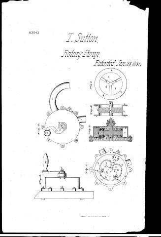
Thomas Sutton's Patent Drawing for a Rotary Pump

National Archives, Restored Patent Drawings (Record Group 241) · Full-size scan at the National Archives · Catalog record
Show the text on the drawing Hide (49 words)
Words on the drawing as machine-read by the National Archives; not checked. Useful mainly for searching.
103 / 103. PUMPS, / Rotary, / CLASSIFICATION / THOMAS SUTTON'S. / Double Pigt / $3, / 1. / 6354.4 63 3 54- X / DIV ISION. / Rotary Pump. / Patented 28th Jan 1831 / Fig1. / 1. / Fight 2. / of / Plank / of / be / Fig's / Fig4. / Fig 6. / Frig 5. / 0. / 0. / s. / fr / Chamber / Outtit / T'
USPTO scan
The patent as scanned by the USPTO
-
 Page 1
-
 Page 2
-
 Page 3
-
 Page 4


U.S. Patent and Trademark Office · Google Patents
Show the transcription Hide (1,495 words)
Machine transcription (LightOnOCR) of the pages as scanned by the USPTO, most of them the handwritten copies made when the records were restored after the 1836 fire. Not checked; it can misread handwriting, so compare it with the scan.
Page 1.
6354X
T. Sutton,
Rotary Pump,
Patented Jan. 28, 1831.

Page 2.
Jan. 28, 1831
6354X Thomas Sutton of Norwich Connecticut
Letters Patent
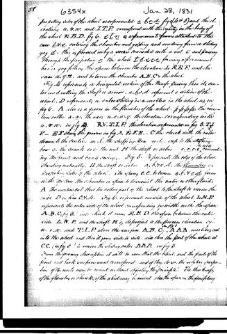
The legislature referred to in these Letters Patent and making part of the same containing a description in the words of the said Thomas Sutton himself of his improvement in the machine called "Sutton's Rotary Pump."
Know all men by these presents that I Thomas Sutton of Norwich in the County of New London and State of Connecticut have invented a new and useful improvement called "Sutton's Rotary Pump," the principle of which improvement may also be applied to steam and other purposes, and that the following is a full and exact description of the construction and operation of said improved machine, reference being had in the following specifications to drawings accompanying and marked "Drawings No. 1." Fig. 1 represents an edge view of the pump attached vertically to a plane: ooooo bolts which fasten together the front and back casings on the crank and handle. a, b, c, d the packing box. e, f the arbor or shaft. m, n nut fastening the crank on the shaft or arbor. Fig. 2 is a front view of the pump. b is the inlet of water or other fluid. a, the outlet. o, o, o, o, o the bolts to confine the two parts of the case together. g, the crank. m, the handle to the crank. f, the shaft or arbor. n, the nut. d, the cap to the packing box. n, d, c represent a projection on the outside of the pump either cast with the pump or attached permanently with screws to the outside and connected with part d (fig. 3). c is a nut attached to a screw passing through this projection and connected with the movable part d (fig. 3). Fig. 3 is a vertical section of the pump showing an inside view of one of the casings. u, v, z, show the outside front case or frame fastened to the back side by bolts o, o, o, o, o to the inlet of the fluid. a, the outlet. A, B, C, the lower surface of one of the casings of the pump. D, D, D, are three valves or slides as represented in fig. 4. D, p, a friction roller by the axis h. (as fig. 4). B, F, I, R, a view or elevation from the lower surface B, F, R is a groove formed by the elevations or raised parts w, w, w and I, T, P, both equally raised from the part B, F, I, R. The first projection from the lower surface A, B, C, to the elevation B, F, I, R, is the precise width of the flanges on
Page 3.
projecting sides of the wheel are represented a. b. c. d. figs (4 & 5) and the elevations a. v. w. and I. T. P. correspond with the cavity in the body of the wheel F. B. D. fig 6. e. t. r. is a permanent frame attached to the case L. S. e. entering the chamber and guiding and rendering firm a sliding gag d. this is pressed in by a screw connected with a nut. c' and passing through the projection e. the whole t. d. e. r. e. forming a permanent bar or gag filling the space between the elevation L. R. E. P. and the case a. v. w. and between the chamber A. B. C. & the wheel.
Fig 4 represents a horizontal section of the Pump passing thru its centre and cutting the shaft or arbor. a. b. c. d. represent a section of the wheel. D represents a valve sliding in a groove in the wheel as in fig 6. A also is a groove in the flanges of the wheel. f. f. f. f. the section roller x. x. the axes a. a. w. y. the elevations corresponding with the a. v. w. in fig 3. R. V. T. I. P. the elevation represented in fig 3. T. I. P. - E. E. shows the groove in fig 3. E. E. R. - C the chuck with the valve thrown to the centre. m. l. the stuffing box. m. c. caps to the stuffing box. a. the crank. e. e. the nut. H the shaft or arbor. c. c. c. c. connecting the front and back casings.
Fig 5. represents the edge of the wheel standing vertically. H the shaft or arbor. a. b. c. d. the flanges or projecting sides of the wheel. the spaces C. C. between a. b. & c. d. form with the case the chamber or space to transmit the water or other fluid. A the meridional line the hollow part of the wheel to the shaft to receive the valve D in figs 3, 4, 5.
Fig 6. represents one side of the wheel I. N. P. represents the outer side of the wheel corresponding in width with the space A. B. C. (fig 3) into which it runs. E. B. D. the space between the outer side I. N. P. and the shaft H is depicted in the previous elevation of a. v. w. and T. I. P. above the surface A. B. C. A A A meridians cut into the wheel and thru it from side to side. also thru the part of the wheel at C. C. (in fig 6) to receive the sliding valve D. D. D. in fig 3.
From the foregoing description it will be seen that the wheel and the parts of the front and back surfaces must correspond and if they do so the relative proportion of the parts may be varied without affecting the principle. The thickness of the flanges or cheeks of the wheel may be varied also the space in the periphery
Page 4.
6354x
Jan 28, 1831
59
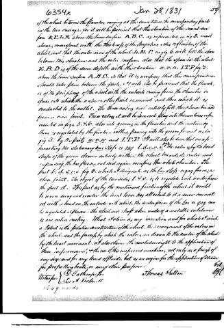
of the wheel between the flanges, carrying at the same time the corresponding parts in the two casings, for it will be perceived that the elevation of the second surface E.E.I.R above the lower surface A.B.C. as represented in fig 3. must always correspond with the thickness of the projecting sides or flanges of the wheel, and that the outer rim of the wheel L.N.P. in fig 6. will fill the space between this elevation and the outer surface, also that the span in the wheel E.B.D is of the same depth with the elevation u.v.u. I.T.P fig 3. above the lower surface A.B.C. so that it is necessary that this correspondence should take place between the parts, & it will also be perceived that the flanges or of the periphery of the wheel with the outside casing form the chamber or space into which the water or other fluid is received and thro which it is conducted to the outlet. The three valves must entirely fill this chamber and form a close joint. These valves it will be seen will play into the motion as represented in figs 5. & 6. also into grooves in the flanges and the motion of them is regulated by the friction rollers passing into the groove formed as in fig 3. by the parts u.v.u. and I.T.P. It will also be seen that on approaching the stationary bar slop as in fig 1. u.v.u. the valve is by the head shape of the groove drawn entirely within the wheel towards its centre and supposing the bar passes out and again occupies the whole chamber. The part L. d. s. v. c fig 3. which I designate as the bar slop or gag forms a close joint. The object of the two sides L. & v. is to regulate and render firm the part d. This part as by the continued friction of the wheel it would be worn away and render the joint loose has attached to it a screw connected with a head on the outside with which the centre piece of the bar or gag can be regulated at pleasure. The wheel and shaft when made of a metallic substance is one entire casting. What I claim as my invention and for which I wish a Patent is the peculiar construction of the wheel, the arrangement of the valves in the wheel, and the process by which the valves are drawn to the centre of the wheel by the head movement. I also claim the exclusive right to the application of these improvements, & the use of this improved machine, not only as a pump of any size and for any kind of fluids, but as an engine for the application of steam for propelling boats, or any other purpose.
Witnesses
D. Rathbone Jr.
Jno. A. Rockwell
1649 words
Thomas Sutton
6/11
1831
Published accounts: journal notice
Notice in the monthly list of patents, with remarks
Journal of the Franklin Institute, new ser., vol. 7 (1831), p. 314 · View the page
40. For a Rotary Pump; Thomas Sutton, Norwich, New London county, Connecticut, January 28.
Remarks. We have described several rotary pumps, and those who are conversant with hydraulic machines, are well acquainted with the principle upon which they in general operate. Toothed wheels taking into each other, or sliding valves variously constructed, are employed for the purpose of raising the water. In the present instance the sliding valves are used, and the mode in which they are moved is extremely ingenious, but a clear and adequate idea of the arrangement would require a view of the drawings. The great objection to most of these plans is a want of simplicity, which causes them to be difficult to make, and very liable to derangement by friction; we fear that these difficulties have not been overcome by the present patentee.
About this record
- Patentee
- DATAMP
- Date
- DATAMP
- Invention
- DATAMP
- Listed in
- the Name and Date index of patents, DATAMP, USPTO records, Jim Shaw's X-patent list, the Journal of the Franklin Institute, Burke's List of Patents (1847)
- The sources give different dates; the date shown is the one most of them agree on.
- The date conflict was settled by Burke's 1847 list.
- The Franklin Institute's journal confirms the date shown.
- Burke's 1847 Patent Office list gives the same patent.
- Burke's 1847 Patent Office list gives a slightly different date; the date shown follows the standard lists.