

Drawings and documents
National Archives restored drawings: drawing
J. Fox and W. G. Borland's Patent Drawing for a Thrashing Machine

National Archives, Restored Patent Drawings (Record Group 241) · Full-size scan at the National Archives · Catalog record
Show the text on the drawing Hide (161 words)
Words on the drawing as machine-read by the National Archives; not checked. Useful mainly for searching.
130. THRASHING. / Thrashing Machines. / A. Cylinder Machines. / T. Fox & W.G. Borland Entered. o / Vol. 12.p.575 / Restored / Patents. / Thrashing Machine / Patented stho Feby 1831, / CLASSIFICATION / 6368- + / DIVISION. / 410 / your / R eferences. / A.A.A.A. the frame. / B.b eater head, or cylinder. C. "Semicircular bed. / Dirollers, through which the grain passes. / E.E. spiral springs. which support the b ed, and yield, / tosticks and stones passing through the machine. / F.F. hand-screws, by which the springs are regulated, / G. long mortise, in which the slide supporting the spural / Palms office 30 lept 1841 / springs moves. up and down. / H. springs, pressing on fluted rollers D.D. between which / Made under the direction of the Commipronce of / the grain passes. I. b allance wheel, on beater head shaft. / K.hopper, through which the grainis introduced, / Patents in conformity with act of bougrip March1857, / Mengh Ellmorth / Commipion of Patents
USPTO scan
The patent as scanned by the USPTO
-
 Page 1
-
 Page 2
-
 Page 3
-
 Page 4


U.S. Patent and Trademark Office · Google Patents
Show the transcription Hide (1,154 words)
Machine transcription (LightOnOCR) of the pages as scanned by the USPTO, most of them the handwritten copies made when the records were restored after the 1836 fire. Not checked; it can misread handwriting, so compare it with the scan.
Page 1.
6368X
Fox & Barland.
Thrashing Mach.
Patented Feb. 8, 1831.

Page 2.
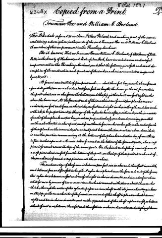
Copied from a Print.
Truman Fox and William G. Borland.
The Schedule referred to in these Petters Patent, and making part of the same, containing a description, in the words of the said Truman Fox and William G. Borland themselves, of their improvement in the Thrashing Machine:
Be it known, That we Truman Fox and William G. Borland, of the Town of Sills Falls, in the County of Herkimer, and State of New York, have invented a new and useful improvement in the Thrashing Machine; and that the following is a full and exact description of the construction and operation of the said machine as invented or improved by us, to wit:
A frame constructed of four posts each about three feet long, in which are framed four side girts, two on each side, about four feet in length; the lower girts are framed in the posts about six inches from the bottom, and the top girts about one foot eight inches above the lower ones. At the forward end of the machine are framed two planks, one on each side, one foot and four inches wide, one foot and eight inches in length and two inches thick, to be proportioned to the size of the cylinder herein after mentioned; on the inner side of each of these planks are two long mortises perpendicularly made and running parallel with each other, ten inches apart, and from three to five inches in length; in the center of each of these planks on the inner side, at a central point between the two mortises above described, is another mortise commencing at the bottom of the plank and extending from three to five inches upward. A cross sill is framed on the bottom of the forward posts; also a cap piece is framed across the top of the same posts. On the hind end of the frame is framed a cap piece about one foot from the bottom of the posts; on the top of these posts at each end of the machine is framed a cap piece across the machine.
The medium size of the frame is between two feet six inches and three feet in width, and between four and five feet in length. A cylinder is placed near the forward end of the frame; this cylinder is between one foot and one foot eight inches in diameter, and is made of wood in solid form or by means of two or more circular heads covered with slabs about three inches thick; through the center of this cylinder passes an iron shaft with its journals resting in boxes on the top girts on each side of the frame; on one end of this shaft is placed a wheel between eight and ten inches in diameter and on the opposite end of this shaft is placed a fly or balance wheel of cast iron, between three feet and three feet six inches in diameter, and weighing between
Page 3.
one hundred and fifty and two hundred pounds. In the cylinder are inserted staple teeth projecting from the surface of the cylinder between one and two inches; these teeth are made of large wire, (number one or two) or of brass rods, and they may be round, square or diamonding; the teeth are inserted in rows lengthwise of the cylinder, the rows being between two inches and a half and three inches apart, and the teeth in the rows the same distance apart. These teeth are so put in, by omission in one row and insertion in another, that a space left for instance in the first row is supplied by insertions in the second and third rows, and so on till the whole cylinder is filled; these teeth, when the cylinder is in motion, pass through teeth also inserted in the concave bed below the cylinder herein after described.
Under the cylinder is placed a receding concave bed formed of wood or metal, reaching from the center of the cylinder below two thirds the distance to the cylinder shaft; there are two tenons on each side of this concave bed, about one third from the center thereof, which act in the long portions above described and recede as relief is required. This bed rests upon springs of wood or iron, under which is framed a slide on which the springs rest, and beneath the slide is framed a bar or cross piece through which screws are run so as to control the spring, in order to regulate the action and position of the concave bed;—this bed can also be regulated by means of levers and weights as well as springs; staple teeth are inserted in this concave bed projecting the same distance from the surface as in the cylinder, and the teeth are formed of like material and in like manner; they are inserted in 3 or 4 rows in such a manner that the teeth in the cylinder when in motion act closely therewith and pass between them.
Near the summit of the concave bed may be placed (or they may be omitted) two fluted rollers from 3 to 6 inches in diameter, their journals (resting in boxes on each side of the frame); on the upper roller springs may be made to press downward on its journals so as to hold the grain while it passes to the operative parts; on one end of the shaft of the upper roller is placed a wheel with different sized grooves to regulate the feeding; also a wheel is placed on the cylinder shaft to which the power to carry the roller is applied.
An inclined box or hopper is placed on the machine, one end resting on the head cap piece and the other placed near the summit of the concave bed; through this box or hopper the grain is introduced to the cylinder and concave bed; a box is also placed on the cylinder, which covers it and prevents grain and straw from flying off.
What we claim as new and our own invention and discovery in the above described
Page 4.
6368x
Feb 8, 1831
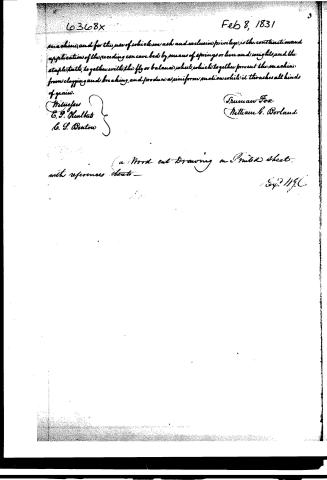
machine, and for the use of which we ask and exclusive privilege, is the construction and application of the reeding concave bed by means of springs or levers and weights, and the staple tails, together with the fly or balance wheel, which together prevent the machine from clogging and breaking, and produce a uniform motion while it thrashes all kinds of grain.
Witnesses
C. P. Hurlbut
C. S. Denton
Truman Fox
William S. Borland
(a Word cut Drawing on Printed Sheet
with references thereto —
Ex. 21196.
Published accounts: journal notice
Notice in the monthly list of patents, with remarks
Journal of the Franklin Institute, new ser., vol. 7 (1831), p. 369 · View the page
10. For a Thrashing Machine; Truman Fox, and Wm. G. Borland, Little Falls, Herkimer county, New York, February 8.
Remarks. We have again a thrashing machine of the ordinary form, with the addition, however, of a fly wheel, which is an appendage not attached to the whole of them; nor is it necessary when the cylinder is weighty and has a very rapid motion. "What we claim is the construction of the receding concave, by means of springs, or lever and weights; and the staple teeth; and the fly or balance wheel." The teeth are formed of wire, and bent so as to drive in at both ends, like a staple: this, we believe, is new, but the other parts claimed have so many previous claimants, that it is impossible to designate the true and original owner, though we can with some confidence say who is not so.
About this record
- Patentee
- DATAMP
- Date
- the Name and Date index of patents, DATAMP, USPTO records
- Invention
- DATAMP
- Listed in
- the Name and Date index of patents, DATAMP, USPTO records, Jim Shaw's X-patent list, the Journal of the Franklin Institute, Burke's List of Patents (1847)
- The Name and Date index lists this patent twice.
- Burke's 1847 Patent Office list gives the same patent.
Shaw: lists Strode, J. C. here as 6368½