

Drawings and documents
USPTO scan
The patent as scanned by the USPTO
-
 Page 1
-
 Page 2
-
 Page 3
-
 Page 4
-
 Page 5
-
 Page 6
-
 Page 7
-
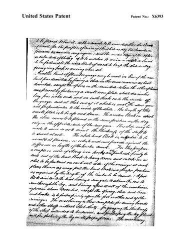 Page 8
-
 Page 9


U.S. Patent and Trademark Office · Google Patents
Show the transcription Hide (3,047 words)
Machine transcription (LightOnOCR) of the pages as scanned by the USPTO, most of them the handwritten copies made when the records were restored after the 1836 fire. Not checked; it can misread handwriting, so compare it with the scan.
Page 2.
United States Patent
Patent No.: X6393
Ruuel Jacobs of Wilton, New York
Letters Patent
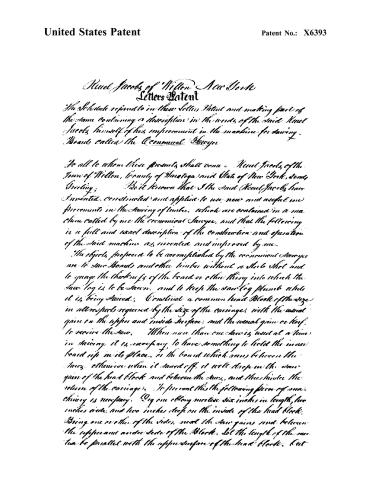
The Schedule referred to in these Letters Patent and making part of the same containing a description in the words of the said Ruuel Jacobs himself of his improvement in the machine for sawing Boards, called the Economical Sawyer.
To all to whom these presents shall come: Ruuel Jacobs, of the Town of Wilton, County of Westchester and State of New York, sends Greeting.
Know ye that I the said Ruuel Jacobs have invented, constructed and applied to use, new and useful improvements in the sawing of timber, which are contained in a machine called by me the Economical Sawyer, and that the following is a full and exact description of the construction and operation of the said machine as invented and improved by me.
The objects proposed to be accomplished by the economical Sawyer are to saw Boards and other timber without a stock shot and to gauge the thickness of the board or other thing into which the saw log is to be sawn, and to keep the saw log plumb while it is being sawed. Construct a common head Block of the size in all respects required by the size of the carriage, with the usual grain on the upper and inside surface, and the usual grain or hoof to receive the saw. When more than one saw is used at a time in sawing, it is necessary to have something to hold the inner board up in its place, in the board which runs between the saws, otherwise when it saws off, it will drop in the saw grain of the head block and between the saws, and thus hinder the return of the carriage. To prevent this the following piece of machinery is necessary. Dig one oblong mortise six inches in length, two inches wide, and two inches deep on the inside of the head block. Bring one or other of the sides, near the saw grains and between the uppermost and under side of the Block. Let the length of the mortise be parallel with the upper surface of the head block. Cut
Page 3.
United States Patent
Patent No.: X6393
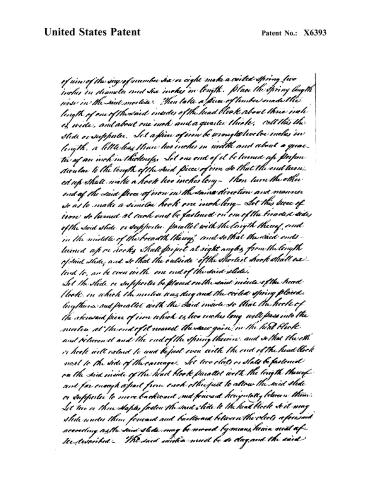
of wire of the size of number six or eight make a coiled spring five inches in diameter and six inches in length. Place the spring lengthwise in the said moles. Then take a piece of timber made the length of one of the said inside of the head block about three inches wide, and about one inch and a quarter thick, call this the slide or supporter. Let a piece of iron be wrought twelve inches in length, a little less than two inches in width and about a quarter of an inch in thickness. Let one end of it be turned up perpendicular to the length of the said piece of iron so that the end turned up shall make a hook two inches long—then turn the other end of the said piece of iron in the same direction and manner so as to make a similar hook one inch long—Let this piece of iron be turned at each end be fastened on one of the broader sides of the said slide or supporter, parallel with the length thereof, and in the middle of the breadth thereof, and so that the said ends turned up or hooks shall project at right angles from the length of said slide, and so that the outside of the shortest hook shall extend to, or be even with one end of the said slide.
Let the slide or supporter be placed on the said inside of the head block, in which the moles was dug and the coiled spring placed lengthwise and parallel with the said inside so that the hooks of the said piece of iron which is two inches long will pass into the moles at the end of it nearest the said gain in the said block and between it and the end of the spring therein, and so that the other hook will extend to and be just even with the end of the head block next to the side of the carriage. Let two slots or slats be fastened on the said inside of the head block parallel with the length thereof and far enough apart from each other just to allow the said slide or supporter to move backward and forward horizontally between them. Let two or three staples fasten the said slide to the head block so it may slide under them forward and backward between the slots aforesaid according as the said slide may be moved by means herein set forth described. The said moles must be so dug and the said
Page 4.
United States Patent
Patent No.: X6393
slate fastened at such a place as will bring the upper edge of the slide or supports about an inch below the log resting on the gain of the head block. For the purpose of constructing the machinery to move the said slide or supports proceed as follows: at the end of the said inside on which the said slide moves, that is nearest to the side of the carriage and at right angles with the length of the said inside, dig a channel or groove about three inches deep and about three inches wide and along the whole length of the said end of the head block, so that the bottom of said channel shall be all the way perpendicular with and at right angles to the said slide. Cut of some hard wood make a piece of timber about six inches longer than the length of the said inside width of the head block, and of a breadth and thickness easily to fit into the said channel or groove. At the distance of about nine inches from one end of the said last mentioned piece of timber which may be called the lever, and on the side of the depth or thickness thereof, shape it equally and gradually to the point or end of the lever so as to make a regular slope, and so that the end of the lever shall be about a half an inch in thickness. Make a piece of iron two inches wide about a quarter of an inch thick and an inch and a half longer than the length of the lever, fasten this lengthwise on the side of the lever opposite the shaven or sloped side, in the middle of that side, and so that one end of the said piece of iron shall project beyond the shaven end of the lever the distance of an inch and a half. Cut this to bone at right angles towards the said gain in the head block, and then bore again at right angles to the nearest side of the slide, so that the piece projecting towards the slide shall be an inch in length, measuring from the last bend or angle. This is intended to meet and act upon the hook upon the end of the slide nearest the side of the carriage. The lever must be fastened into the channel or groove in the end of the head block by a pin put through a hole bored through the sides of the gain or channel and through the lever parallel with the end of the head block, and at a distance of about
Page 5.
United States Patent
Patent No.: X6393
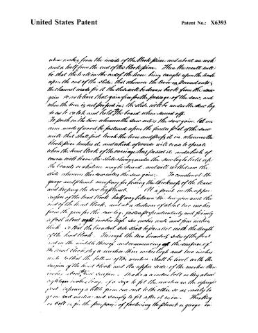
when it comes from the inside of the block piece and about an inch and a half from the end of the block piece. Then the result will be that the tooth in the end of the lever, being caught upon the hook upon the end of the slide, that whenever the lever is pressed onto the channel made for it the slide will be drawn back from the saw again so as to leave that gain free for the passage of the saw, and when the lever is not pressed in, the slide will be under the saw log so as to catch and hold the board when sawed off.
To push in the lever whenever the saw enters the saw gain, let an arm made of wood be fastened upon the front foot of the saw mill that shall just touch the lever and press it in, whenever the block piece touches it, and which of course will cease to operate when the head block of the carriage has passed it, and which of course will leave the slide always under the saw log to hold up the boards or whatever may be sawed, and will withdraw the slide whenever the saw enters the saw gain.
To construct the gauge and plumb necessary for fixing the thickness of the board and keeping the saw log plumb. At a point in the upper surface of the head block half way between the saw gain and the end of the head block, and at a distance of about two inches from the gain for the saw log, fasten perpendicularly and firmly a post about eight inches high six inches wide and four inches thick so that the broadest side shall be parallel with the length of the head block. Through the two broadest sides of the post cut in the middle thereof and commencing at the surface of the head block, dig a mortise three inches high and two inches wide so that the bottom of the mortise shall be level with the surface of the head block and the upper side of the mortise three inches above the surface. Make a wooden bolt or key about eight or ten inches long, of a size to fit the mortise in the upright post, tapering a little from one end to the other so as easily to go in and out and snugly to fit after it is in. This key or bolt is for the purposes of fastening the plumb or gauge in
Page 6.
United States Patent
Patent No.: X6393
Marginal function. The plumb square is constructed as follows: Take a hard piece of timber two feet long, ten inches wide and four inches thick. At the distance of ten inches from one end saw through the width of said piece of timber perpendicularly to within three inches of the opposite edge or side, then leave the piece which is ten inches in width and length and cut down the other the whole of its length as low down as the saw cut. You will then have what may be called the plumb or gauge, and one part of it will be three feet two inches long, three inches deep and four inches wide with its upper surface smooth and parallel with its under surface. The other part of it will be of a convenient inches square, let the under corner of this square piece be cut off so as to prevent the saw dust from clogging the plumb. For the purpose of having a convenient place to put the boards so when sawed erect and fasten a small post in the upper side of the gauge near the small end and of a height equal to the upper surface or edge of the square or large end of the plumb. On the said upper edge of the square end and on the top of this post fasten a small bar or rail of convenient size and length. In this the sawed boards may be thrown while the sawyer is sawing, until he can have time to remove them to other proper places.
The gauge or plumb is to be fastened on the grain of the head block which the saw log rests upon and parallel with the length of the head block and is fastened to any desired point by passing the large bolt through the mortise in the upright post standing on the head block and over the plumb. By means of this boards or other stuff may be sawed of any desired thickness.
For the purposes of constructing dogs to hold the saw log in its position proceed as follows: Take a block of hard timber one foot and a half long and four inches square. On one side thereof and parallel with the length thereof fasten firmly a cast iron plate of equal length thick, one inch in thickness and six inches in width and let the ends of the plate be even with
Page 7.
United States Patent
Patent No.: X6393
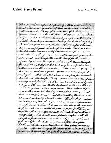
The ends of the block of wood respectively. Make a cast iron slide about eight inches long and about three inches thick and about eight inches wide. A row of the wide sides of this is a groove or channel be cast, on which the plate on the top of a wooden block may be inserted so that the slide or dog may move thereupon and the channel or groove must be so cast as to touch and hug the cast iron plate on the underside of the edges of it which extend over and beyond the sides of the wooden block so that the slide or dog may more easily latchwards and forwards, but not otherwise. Through this cast iron slide or dog let four or five holes be cast, and through the width thereof for the purpose of inserting wrought iron nails which may be driven through them into the leg to keep it fast and may be easily taken out with an iron crow bar or mule bar. These nails or spikes should be about one inch and a quarter square and about one foot in length. If it should be deemed necessary for the further security and steadiness of the leg, two additional spikes of similar size may be put through holes, made and secured by iron casings or sleeves, in the block of wood, on the iron plate of which the cast iron slide or dogs move. These should be put as near that end of the block of wood which comes nearest to the rear as their firmness and the strength of the wood will allow and on directly above the other. This block of wood and its casings complete the dog or slide, and must be fastened on the upper side of the head block and on that side of the rear which is opposite the one on which the plumb or gauge is placed lengthwise thereon and parallel with the length thereof so that the side of the dog shall be in the same plane or surface with the upright or perpendicular side of the iron leg gain, and one end of it must just touch the nearest side of the rear gain. Let this end be the one in which the additional spikes or nails are inserted. The under edge of the inside of the slide or dog shall be cast with small keys so as to fit a small cast iron wheel
Page 8.
United States Patent
Patent No.: X6393
to be placed below it, with a handle to be inserted into the block of wood, for the purpose of turning the slide or dog backwards, or forwards as occasion may require, and the under edge of the other or outer side of the log is to be notched to receive a catch or hook to be fastened to the said block of wood to keep the slide or dog from going back or moving when set.
Another kind of lumber gauge may be made in lieu of the one just before described, by fixing a slide in the same manner as last described, except the spars, on the same side where the other spars were placed by fastening a small iron plate about six inches long, four inches wide and an inch thick on to the inside of the gauge, and at that end of it which is next the saw-gain and perpendicular to the inside of the slide. The length of this small plate is to be up and down. The wooden block on which the slide moves to be placed in the same position as the dog only on the opposite side of the saw-gain. This slide may be made to move so as to direct the thickness of the stuff to be sawed at will. The whole head block is intended to be movable at pleasure, in order not only to provide against the difference in length of the timber sawed. For this purpose a couple or more of strong iron hooks are fastened firmly to each end of the head block to hang down and catch in a cleat to be fastened on each out side of the carriage at such places therein as may put the head block in a proper position as required by the length of the timber to be sawed. A foot block similar to the head having a saw-gain to allow the saw to saw through the log, and having upon it all of the machinery herein above described, except the spring, slide, and lever and hooks, is to fasten firmly upon the foot or other end of the carriage. The machinery is then complete for sawing boards and other stuff without slabs. Not only for gauging the thickness of the stuff intended to be sawed, and for keeping the log plumb, and for fastening the log in its proper place. The machinery
Page 9.
United States Patent
Patent No.: X6393
for these several purposes may be used separately or together as may be thought best, as either may be used without the other, and the improvements for such purposes as hereinabove set forth the said Reuel Jacobs claims as his — In witness whereof he hath hereunto set his hand and seal this 11th day of September in the year of our Lord One Thousand Eight Hundred and thirty.
Reuel Jacobs.
Test:
Wm. Hughes
Chas. J. Giles
Thomas Palmer
(3068 01021)
Published accounts: journal notice
Notice in the monthly list of patents, with remarks
Journal of the Franklin Institute, new ser., vol. 7 (1831), p. 376 · View the page
34. For an improvement in the Sawing of Boards by means of a machine called the Economical Sawyer; Reuben Jacobs, Wilton, Saratoga county, New York, February 22.
Remarks. "The objects proposed to be accomplished by the economical sawyer, are to saw boards and other timber without a stubshot, and to gauge the thickness of the board, or other thing, into which the American Patents for February, with Remarks. saw log is to be sawn, and to keep the saw log plumb while it is being sawed." The mode of effecting these objects is particularly explained in the specification; the head blocks of the carriage of a common saw mill have the dogs so constructed and arranged, and there is a rack and pinion for the purpose of moving the log, constructed in such a way as to attain the proposed ends. The claims are to the particular parts represented as the invention of the patentee.
About this record
- Patentee
- DATAMP
- Date
- the Name and Date index of patents, DATAMP, USPTO records
- Invention
- DATAMP
- Listed in
- the Name and Date index of patents, DATAMP, USPTO records, Jim Shaw's X-patent list, the Journal of the Franklin Institute, Burke's List of Patents (1847)
- Burke's 1847 Patent Office list gives the same patent.