

Drawings and documents
National Archives restored drawings: drawing
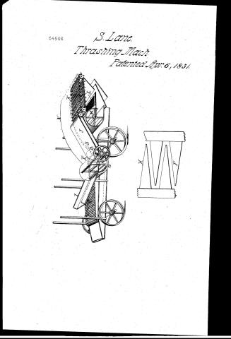
Samuel Lane's Patent Drawing for a Grain Thrasher and Cleaner

National Archives, Restored Patent Drawings (Record Group 241) · Full-size scan at the National Archives · Catalog record
Show the text on the drawing Hide (42 words)
Words on the drawing as machine-read by the National Archives; not checked. Useful mainly for searching.
130. THRASHING. / Grain Separators. / A. Straw Carriers. / Entered oro / Endless Apron. / SAMUEL LANE'S / GRAIN THRASHER,AND CLEANER . / CLASSIFICATION / 6450-4 / Patented 6ᵗʰApril 1831. / DIVISION. / du / FEE / b/B.
USPTO scan
The patent as scanned by the USPTO
-
 Page 1
-
 Page 2
-
 Page 3


U.S. Patent and Trademark Office · Google Patents
Show the transcription Hide (705 words)
Machine transcription (LightOnOCR) of the pages as scanned by the USPTO, most of them the handwritten copies made when the records were restored after the 1836 fire. Not checked; it can misread handwriting, so compare it with the scan.
Page 1.
6450X
S. Lane.
Thrashing Mach.
Patented Apr. 6, 1831.
Page 2.
Samuel Lane
Letters Patent
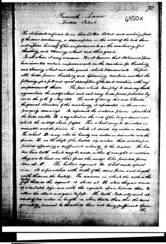
The Schedule referred to in these Letters Patent and making part of the same containing, a description in the words of the said Samuel Lane himself of his improvement in the machinery for threshing, and cleaning wheat and other grain.
To all whom it may concern. Be it known that I Samuel Lane have invented certain improvements on the machine for threshing and cleaning wheat and other grains which I demonstrate the portable horse power threshing and cleaning machine and that the following is a full and exact description of the said machine with my improvements thereon. The power which I employ to drive my threshing machine the endless chain and rail way horse power patented by me on the 17th of May 1830. The mode of doing this and likewise the general structure of the machinery is represented in the accompanying drawings. A represents the inclined plane upon which the horse walks. B. a cog wheel on the end of the larger drum over which the endless chain passes. This wheel may be 21 inches in diameter and the pinion C. which it drives six inches in diameter. The wheel D. may also be twenty-one inches in diameter and the pinion E. on the shaft of the beaters six inches. These relative proportions affording, a sufficient velocity to the beaters. The beaters have teeth which may be made either of wrought or cast iron they are to have on their faces the wedge like pointed form, seen at F. The hollow segment G. is best made of cast iron. It is furnished with teeth of the same form and length with those on the beaters. The manner in which the teeth on the top those on the segment is shown at H. where they are drawn of a suitable size, and with the requisite space between them, to allow the straw and grain to pass. The teeth (gradually) make up more of two inches in length as, when shorter than this the same quantity cannot be threshed there not being sufficient space.
Page 3.
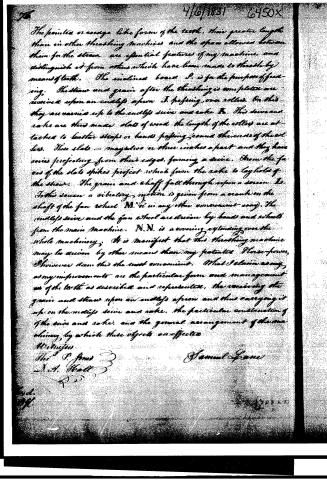
The pointed or scythe like form of the teeth, their greater length than in other threshing machines and the space allowed between them for the straw are essential features of my machine, and distinguish it from others which have been made to thresh by means of teeth. The inclined board P. is for the purpose of feeding. The straw and grain after the threshing is complete are received upon an endless apron I passing over rollers. On this they are carried up to the endless sieve and cake R. This device and cake are thus made slats of wood the length of the rollers are attached to leather straps or bands passing around the ends of the rollers. These slats are maybe two or three inches apart and they have spines projecting from their edges forming a sieve. From the faces of the slats spikes project which form the cake to lay hold of the straw. The grain and chaff fall through upon a screen I. To this screen a vibratory motion is given from a crank on the shaft of the fan wheel M. (or in any other convenient way). The endless sieve and the fan wheel are driven by bands and wheels from the main machine. N.N. is a covering extending over the whole machinery. It is manifest that this threshing machine may be driven by other means than my patented Horse-power, I however deem this the most convenient. What I claim as my improvements are the particular form and management of the teeth as described and represented, the receiving the grain and straw upon an endless apron and thus carrying it up on the endless sieve and cake, the particular construction of the sieve and cake, and the general arrangement of the machinery, by which these objects are effected.
Witnesses
Wm. P. Jones
J. A. Hall
Samuel Lane
Published accounts: specification
Specification printed in the Journal of the Franklin Institute
Journal of the Franklin Institute, new ser., vol. 7 (1831), p. 270 · View the page
Text of the specification as printed in the Journal, from OCR; not proofread.
Specification of a patent for a machine for Thrashing and Cleaning Wheat and other grain. Granted to SAMUEL LANE, Hallowell, Kennebeck county, Maine, April 6, 1831. Lane's Thrashing and Winnowing Machine. Fig. 1. N To all whom it may concern, be it known, that I, Samuel Lane, have invented certain improvements on the machine for thrashing LANE'S Thrashing and Winnowing Machine. Fig. 2. and cleaning wheat and other grain, which I denominate the portable horse power thrashing and cleaning machine, and that the following is a full and exact description of the said machine with my improvements thereon. The power which I employ to drive my thrashing machine is the endless chain, and railway horse power, patented by me on the 17th of May, 1830. The mode of doing this, and likewise the general structure of the machine, is represented in the accompanying drawings. A, Fig. 1, represents the inclined plane upon which the horse walks. B, a cog wheel on the end of the larger drum, over which the endless chain passes. This wheel may be 21 inches in diameter, and the pinion, C,* which it drives, 6 inches in diameter. The wheel, D, may also be 21 inches, and the pinion, E, on the shaft of the beaters, 6 inches; these relative proportions affording a sufficient velocity to the beaters. The beaters have teeth, which may be made either of wrought or cast iron; they are to have, on their faces, the wedge-like, pointed, form seen at F, Fig. 2. The hollow segment, G, is best made of cast iron. It is furnished with teeth of the same form and length with those on the beaters. The manner in which the teeth on the beaters pass those on the segment is shown at H, F, Fig. 2, where they are drawn of one-fourth of their usual size, and of the requisite space between them to allow the straw and grain to pass. The teeth I usually make upwards of two inches in length, as when shorter than this, the same quantity cannot be thrashed, there not being sufficient space. The pointed, or wedge-like, form of the teeth, their greater length than in other thrashing machines, and the space allowed between them for the straw, are essential features of my machine, and distinguish it from others which have been made to thrash by means of teeth. The inclined board, I, is for the purpose of feeding. The straw and grain, after the thrashing is completed, are received upon an endless apron, J, passing over rollers. On this they are carried up to the endless sieve and rake, K. This sieve and rake are thus made-slats of wood, the length of the rollers, are attached to leathern straps, or bands, passing round the end of the rollers. These slats may be two or three inches apart, and they have wires projecting from their edges, forming a sieve. From the faces of the slats spikes project which form the rake to lay hold of the straw. The grain and chaff falls through upon a screen, L. To this screen a vibratory motion is given, from a crank on the shaft of the fan wheel, M, or in any other convenient way. The endless sieve, and the fan wheel, are driven by bands and whirls from the main machine. N, N, is a covering extending over the whole machinery. It is manifest that this thrashing machine may be driven by other means than my patented horse power; I, however, deem this the most convenient. * B and C are a wheel and pinion on the opposite end of the machine. High Pressure Steam Engines. What I claim as my improvements are the particular form and arrangement of the teeth as described and represented; the receiving the grain and straw upon an endless apron, and thus carrying it up on the endless sieve and rake; the particular construction of the sieve and rake, and the general arrangement of the machinery by which these objects are effected. SAMUEL LANE. We have caused to be translated for the Journal the various ordinances, issued since 1823, of the French government in relation to high pressure steam engines. The ordinances are accompanied by circulars, explanatory of their details, and which emanate from different boards composed of officers of the corps of mines, and of government civil engineers, selected with reference to their peculiar qualifications for the task imposed. [Сом. Рив. Royal Ordinance of France, in relation to High Pressure Steam Engines, followed by instructions, and a Circular, on the same subject. 1823. [TRANSLATED FOR THIS JOURNAL.] Ordinance relating to High Pressure Steam Engines. ART. 1. High pressure steam engines, those in which the elastic force of the steam exceeds two atmospheres, whether they consume their own smoke or not, cannot be set up except by virtue of authority obtained in conformity with the decree of 15th October, 1810, for establishments of the second class. They will, besides, be subject to the following conditions, imposed in order to insure safety. Art. 2. When authority for setting up such an engine is requested, the individual requesting authority must state at what degree of pressure the engine is to be worked. Such pressure must not be exceeded. The pressure must be stated in atmospheres, or in the number of pounds to each square inch of surface exposed to the pressure of the steam. Art. 3. No high pressure boiler can be used unless it has been previously subjected to trial by the hydraulic press. Every boiler must be proved at five times the pressure under which the engine supplied by it is to work. Every boiler shall be marked after being proved, with a number, expressing the pressure under which it may be used, corresponding to the proof. No individual shall use a boiler which is not marked with a number at least equal to that representing the pressure under which he has stated, in his declaration, that the boiler is to be used. Art. 4. There shall be two safety-valves placed upon the top of every boiler, one at each end. The size and load of each shall be the same, and must be regulated, the former by the size of the boiler, the latter by the degree of pressure indicated by the proof-mark: the size of either valve will be so regulated that if raised alone, it may be sufficient to discharge the steam accumulated within the boiler. The first valve shall be under the control of the engineer or fireman. The second must be preserved from such control by being inclosed in a grating, of which the proprietor of the works, where the engine is used, shall have the key. Art. 5. There shall in addition to these valves, be adapted to the top of each boiler two metallic plates, fusible at temperatures hereinafter to be stated. The first of an area at least equal to that of one of the safety valves, shall be made of an alloy which shall melt, or soften so much as to yield to pressure, at 10 degrees of the Centigade thermometer, (18°F.) above the temperature corresponding to the proof-mark upon the boiler. The second of twice the area of the first, shall be placed near and inclosed by the same grating, with the first safety valve: it shall be made of an alloy which shall fuse, or soften, at 20° C. (36 F.) above the proof-mark. These plates shall be stamped with a number showing the degree of the thermometer at which they fuse. Art. 6. No boiler shall be placed in an inclosure of less than twenty-seven times the capacity of the boiler. The inclosure must be lighted, on two sides at least, by windows, closed by light shutters, opening outwards. It must not be contiguous to the walls of adjacent buildings, from which it must be separated by a wall of at least three feet thick, distant not less than two yards from the building. It must be separated by a wall of the same thickness from any interior workshop. There must be neither dwelling nor workshop above the boiler house. Art. 7. The engineers of mines resident in the several departments, or in their default the government civil engineers, are charged with superintending the proving of the boilers, and fusible plates. They will stamp the proof numbers upon them with dies, which are to be furnished them for that purpose. These engineers shall satisfy themselves, by inspection, at least once every year, that all the conditions prescribed are rigorously observed. They must examine the boilers, ascertain their condition, and cause to be thrown out of use, those which long continued wear, or accidental deterioration, may have rendered dangerous. The local police authorities will keep a constant watch over the works using high pressure engines. In case of non-compliance with the present ordinance, the proprietors of the works will be subject to a stoppage of the works, without regard to the penalties, damages, &c. which may be awarded by the courts of justice. Art. 8. Our minister of the interior will cause instructions to be VOL. VII. No. 4, APRIL, 1831. 35 published, stating the precautions to be habitually observed in relation to high pressure engines. These instructions must be posted up in the works. Art. 9. Our minister of the interior is charged with the execution of this ordinance, which will be inserted in the Bulletin of Laws. Given, &c. Oct. 29th, 1823. [Signed,] CORBIERE, Minister of the Interior. LOUIS. Instructions relating to the precautions to be observed in the use of High Pressure Steam Engines. THE use of high pressure engines requires constant care on the part of the engineers and firemen, and constant watchfulness on that of the proprietors. By neglecting the necessary precautions, the workmen may give rise to serious accidents, of which they themselves will be the first victims. By relaxing in vigilance the proprietors of the works may be the indirect cause of such accidents, besides exposing themselves to the losses which must result from the destruction of the engine, and to the injury which their business must suffer from the stoppage of work. It is the duty of the proprietor to trust the direction of the engine to none but a man of tried intelligence and capacity, who is not only sober, and active, but who is also without any impediment to the regular discharge of his duty. Nothing should interfere with this regularity, nothing disturb or distract the attention of the engineer, otherwise there can be no security in the works. The attention of the engineer and proprietor should be directed particularly to the following parts of the engine, viz: the furnace, the boiler, and boiler-tubes, the supply pipe, the level of the water within the boiler, the safety valves, the gauge. There are precautions to be taken also in relation to the inclosure containing the boiler. The Furnace. The principle according to which the heating should be regulated, is to avoid sudden changes of temperature, from cold to heat, or the reverse; in either case, the boiler is exposed to more or less considerable inequalities of temperature, which, on account of the variable expansions caused, may occasion cracks and leaks. Thus, on first getting up the steam, the fire should not be urged too much, particularly if the furnace has been entirely cold. Time would be gained only at the expense of the safety of the boiler. When the fire has been raised to a height adequate to supply steam for the working of the engine, it ought to be kept up uniformly; it should, therefore, be stirred at proper times, and supplied with just the requisite quantity of fuel, and no more. The fire must not be suffered to go down during the continuance of the work; and if this should happen, fuel must not be supplied hastily, and in great quantities; such a supply would at first produce a chilling effect, and afterwards give out an excessive and dangerous quantity of heat. The stirring and replenishing should be performed quickly, so as to abridge the destructive action, which the cold air, introduced through the furnace door, would otherwise have, upon the boiler. These precautions are not required when the self-regulating apparatus for feeding the furnace with coal, is used; in such a case the fireman must see that the hopper is supplied with coal, and that the supply from it is uniform and continuous. Putting out the fire, when not carefully performed, is one great cause of the accidents which happen to boilers. The best method is to leave the unburned part of the fuel in the furnace, to close the register in the chimney, as well as the door of the ash-pit, and to stop up the crevices of this door, as well as of the furnace door, with clay. By proceeding thus, the sudden cooling of the boiler, and the rapid oxidation of its exterior surface, are avoided. Besides, the unburned fuel is turned to account; for, not having a supply of air, it goes out, and may be readily withdrawn from the furnace when it has cooled. Of the Boiler. However pure, water may seem to be, it deposits an earthy sediment which should not be allowed to accumulate. This deposit rapidly hardens, and increasing in thickness, it prevents the ready access of heat to the water within the boiler: thus, to supply the engine with steam, the fire must be raised, fuel is wasted, and the danger of decay and of bursting is increased. Experiment has shown, that if potatoes in proper quantities be introduced within the boiler, the deposit is for a time prevented, the fecula of the potatoes keeping in suspension, the earthy sediment; but the viscous matter thus formed, as it increases in thickness, hinders the evolution of steam, and a period arrives, when its removal is indispensable; this period depends upon the nature of the water used. The proprietors of the engine should determine, by experiment, the proper period for cleansing the boiler, and also the least possible quantity of potatoes, if used, which will produce the desired effect. These investigations are required, not only by a regard to safety, but to economy; since the action of the fecula will retard the production of steam. If, notwithstanding every precaution, a boiler-tube* should crack, the engineer ought, at once, to inform the proprietor of the fact, and the latter should instantly replace the cracked tube by a new one. Patching the tube would only conceal the mischief, and the danger of explosion would be incurred. The proprietor and engineer should observe, attentively, the oxidation of the surfaces of the generating tubes, particularly if they be of cast iron. If they find reason to suspect that any of their boiler tubes are defective, they should prove them anew without waiting for the visit of the inspecting engineer. The same remarks apply to boilers; but as the means of observation are not so frequent, the engineer and proprietor should seize every occasion to ascertain the condition of the boiler; when, for example, one or more of the • The tubes here referred to, are those below the boiler in Woolf's engine. generating tubes are to be replaced-when repairs are to be made to the covering of the boiler, or when it is emptied to be cleaned, the indications afforded by leaks, should be carefully attended to.When a leak is found at the juncture of the boiler head with the boiler, or at the head of one of the generating tubes, no attempt should be made, while the engine is in action, to close the joint by tightening the screws; by so doing, a risk would be run of cracking the head; in the event of its giving way, the workman would be killed by the splinters, or scalded by the steam and hot water. When the generating tubes, or boilers, are to be cleaned, the proprietors should not require their workmen to let off the water while yet hot, particularly when the boiler tubes have not stop-cocks attached to them. Of the Supply Pump, and the level of the water within the Boiler. When a float is used to show the level of the water within a boiler, it is of the greatest importance that the level should be kept at that indicated by the horizontal position of the lever, attached to the float. The engineer must not, however, trust entirely to the horizontal position of this lever, for information; he must satisfy himself that the motion of the float is perfectly free. He must especially be certain that the stuffing, through which the stem of the float passes steam-tight, does not press too closely upon the stem, preventing its free motion, and rendering inaccurate the indication afforded by the float. The same precautions are necessary, when the float, by its depression, opens a valve through which water is supplied to the boiler as it is wanted. The supply pump should be carefully attended to. If, from negligence, the level of the water within the boiler should become too low, as soon as it is ascertained, the supply should be gradually increased, otherwise accident may result. The water rising rapidly in contact with the sides of the boiler, which the fire may have heated, might produce so great a supply of steam, that the pressure would be too powerful for the boiler to withstand. The danger would be imminent if, in such a case, the safety valves were out of order, or overloaded. If an explosion should not be produced by a defective supply of water, the least evil which could occur would be the fracture of the boiler. Safety Valves. In the engines where these valves are under the control of the fireman, he should study their play, and ascertain exactly what degree of adhesion they have to the valve seats. This adhesion must be attended to, even when the surface of contact is very small. The fireman should satisfy himself, by frequent trials, that these valves have the freedom of motion necessary to their perfect working. In order to this, he should raise, from time to time, the arm of the lever, to which is attached the constant weight with which the valve is loaded, to ascertain that the valve has not acquired an adhesion to its seat. When the valves do not move freely, and when the maximum load which they are to bear, is placed upon them, they can fulfil their object but imperfectly; they confine the steam which should be suffered to escape; it accumulates, and may perhaps acquire an elasticity greater than that which the boiler can resist. This fatal effect might also be produced, if, in order to work the engine more rapidly, a weight has been added to that which constitutes the proper load of the safety valve. To overload the safety valve is exceedingly dangerous; ignorance of the danger incurred would constitute the only excuse for a proprietor who should order such a thing to be done, or for the engineer who should execute such an order. The firemen ought to be well aware, that one of the chief effects of an explosion would be to allow the escape of an immense quantity of hot water and steam, which would cause their death, or inflict extreme suffering. Such accidents are much less to be feared in engines established in conformity with the royal ordinance of October 29, 1823, but the safety valves should not the less be watched, and kept perfectly free. In fact, if their play were stopped, ever so little, it would happen, upon the least increase of the fire, that the steam, instead of escaping, would accumulate, increasing in both temperature and elasticity; it would, after a time, melt the fusible plates applied to the boiler, the working of the engine would be thus stopped, and the proprietor must incur the inconvenience of the delay incident to the replacing of this plate. The proprietor should specially visit every day the valve under the grating of which he has the key. The valves should be ground
Published accounts: journal notice
Notice in the monthly list of patents
Journal of the Franklin Institute, new ser., vol. 7 (1831), p. 270 · View the page
I do not claim to have invented any part of the machinery applied to this manufacture; but what I claim as new, is the manufacturing of spoons, without either casting or forging, by cutting and raising them out of sheet metal, in the way herein described; the same being a new manufacture. ROBERT BUTCHER. Specification of a patent for a machine for Thrashing and Cleaning Wheat and other grain. Granted to SAMUEL LANE, Hallowell, Kennebeck county, Maine, April 6, 1831.
Published accounts: journal notice
Notice in the monthly list of patents
Journal of the Franklin Institute, new ser., vol. 8 (1831), p. 111 · View the page
9. For a machine for Thrashing and Cleaning Wheat and other grain; Samuel Lane, Hallowell Kennebeck county, Maine, April 6.
About this record
- Patentee
- DATAMP
- Date
- the Name and Date index of patents, DATAMP, USPTO records
- Invention
- DATAMP
- Listed in
- the Name and Date index of patents, DATAMP, USPTO records, Jim Shaw's X-patent list, the Journal of the Franklin Institute, Burke's List of Patents (1847)
- Burke's 1847 Patent Office list gives the same patent.