

Drawings and documents
National Archives restored drawings: drawing
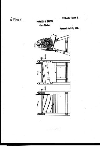
J. Parker and H.M. Smith's Patent Drawing for a Corn Sheller


National Archives, Restored Patent Drawings (Record Group 241) · Full-size scan at the National Archives · Catalog record
Show the text on the drawing Hide (146 words)
Words on the drawing as machine-read by the National Archives; not checked. Useful mainly for searching.
Sheet 1. 130 / 130. THRASHING. / Corn Shellers. / Volulz. Hage 55/- / [59 / Breast and Cylinder. / 62 / Br. theye / J. PARKER T.M SMITH / Corn Sheller / 2 Sheets, Sheet 2. / Front / (Patented) "an' 1831mg / CLASSIFICATION / 6466-7 / DIV ISION / a. Posts / b. Cylinder / C. Ironplates 07' Ribs / d. Pinion / e. Spur Wheel / f. crank shaft / I. Leger forming bollom of Hoppers / h. Board forming side of Horner / i. Perpendicular wood springs / K. Revolving stay girth / l. Sline girth / m. spout / Section / Section / Palent office Febry 22.18420 / Made under the disection of the commmysoer of Patents / in confirmily with ach of 3"March 1837- / Cerichland Del' / Mangh Eurorth / Commynover of Patent
Sheet 2. 130 / 130. THRASHING. / [59] / Corn Shellers. / Breast and Cylinder. / Brtayl O sith / 2,Sheets,Sheet 1. / pl- / J O o PARKER and H.M. SMITH / 6466-+ CLASSIFICATION / CORN SHELLER / Patented I th Apr 9th 1831. / DIVISION
USPTO scan
The patent as scanned by the USPTO
-
 Page 1
-
 Page 2
-
 Page 3
-
 Page 4
-
 Page 5
-
 Page 6
-
 Page 7


U.S. Patent and Trademark Office · Google Patents
Show the transcription Hide (2,033 words)
Machine transcription (LightOnOCR) of the pages as scanned by the USPTO, most of them the handwritten copies made when the records were restored after the 1836 fire. Not checked; it can misread handwriting, so compare it with the scan.
Page 1.
6466X PARKER & SMITH.
Corn Sheller.
2 Sheets—Sheet 1.
Patented April 9, 1831.
N. PETERS, Photo-Lithographer, Washington, D. C.
Page 2.
6466x
PARKER & SMITH.
Corn Sheller.
2 Sheets—Sheet 2.
Patented April 9, 1831.

Page 3.
64606X
April 9 1831
Sabey Parker & Hiram M. Smith
Letters Patent
The Schedule referred to in these Letters Patent and making part of the same containing a description in the words of the said Sabey Parker and Hiram M. Smith themselves of their improvement in the Machine for shelling Corn
To All To Whom These Presents Shall Come Be it known that we Sabey Parker and Hiram M. Smith of the City of Richmond and State of Virginia have invented new and useful improvements in a Machine for shelling Corn and that the following is a full and exact description of the construction and operation of the said Machine as invented or improved by us. This Machine consists of a frame, a cylinder, gear wheels, a hopper, a spout, crank &c. The frame is two feet 5½ inches long and 3 feet 4 inches wide at its feet. It consists of four posts 3 feet 6 inches long 3 inches square and of five girts formed together in the following manner: Two pairs at each end of the Machine are placed together in a triangle form; they are lashed together at the top and come to a point and fastened together by bolts and nuts. The feet spread two feet four inches, forming a complete brace. Each of these two pairs have a cross girt three inches square tenoned through them three inches from their feet and are secured by pins. These two end frames are connected together by three girts 2 feet 2½ inches long exclusive of tenons & 3 inches square. One of which is tenoned into the left hand posts on the hopper side six inches from their feet and immediately above the cross girts. One other is tenoned into the cross girts three inches from the right hand posts and the other one is tenoned into the right hand posts one foot four inches from their feet which girts are secured by pins or bolt screws. Two feet six inches from the feet and one foot from the left in the centre of the right hand posts, is the cylinder shaft upon which the cylinder is hung. Which shaft is of wrought iron and is 2 feet 7½ inches long and 7½ or 8 inches square. It has bearings tenoned at each end.
A. C. C.
Page 4.
end 2½ inches long. On the crank end of this shaft is maybe put on either end is a spur pinion 4 inches in diameter and one inch thick with a hub projecting half an inch which pinion has 15 cogs and is fitted firmly upon the shaft and square with the end of the cylinder, and the hub even with the shoulder of the bearing. The cylinder is two feet long 13 inches in diameter at each end, it is gradually diminished in the centre one eighth of an inch or sufficient to bring it when hung at equal distance from end to end from the ladder in its declining position with the side of the cylinder. The cylinder is made of a solid stick of oak or other seasoned hard wood or of seasoned oak or other hard wood plank and slabs 1½ inch thick. When made of plank and slabs, the heads are 4 lines thickness with their grains seasoned to prevent splitting and are nailed or screwed together. These heads are fitted firmly upon the shaft at their proper places and are then turned upon the shaft to such size as with the thickness of the slabs will make the size of cylinder wanted. The slabs are three or four inches wide, their edges are jointed beveling like barrel slabs, their ends hollowed and fitted upon the heads and are placed close together and nailed or screwed firm to the heads. The cylinder is then turned in a lathe or on its declined place to make to the size and dimension before stated. Eight iron plates or ribs are placed spirally and at equal distance from each other upon the cylinder, extending from end to end with their thick edges to the left or towards the hopper and are made fast to the cylinder by screws or nails. These rods are half an inch wide and 3/4 or ¾ of an inch thick on one edge and half that thickness on the other edge, and two inches of their foot ends are bent to the right or towards their thin edge forming a knee, the ends being turned one inch from the straight line of the rod. To find where to place these rods upon the cylinder make a dot at the crank end of the cylinder from which strike a direct line to within 1½ inch of the other end and from thence measure back to the right upon the surface 9½ inches and make another dot and place the end of the plate or rod upon the first dot and the knee upon the 2nd and same is done and the other rods are placed in
Page 5.
the same direction of the first and at equal distances from each other, three and a quarter inches above the cylinder shaft and near the upper or outer edge of the right hand posts is the crank shaft which is of round or square wrought iron 3/4 or 7/8 of an inch in diameter and has a bearing turned at the foot end 1/2 inch long and one on the crank end three inches long; it passes through the post and has a crank upon the end; it is secured to the posts by caps and screws; one half of the diameter of the shaft being let into the posts and the other half into the caps. Upon this shaft immediately over the pinion on the cylinder shaft is a spur wheel 12 inches in diameter and one inch thick in rim and 1/2 inch at hub. It has 45 cogs which gear into the pinion by which, and the crank on the end of this shaft the machine is put in operation, and which gives the cylinder three revolutions to one of the cranks. Upon the outside of the left hand posts at the side of the cylinder is a ledger, the bottom of which runs parallel with the cylinder and the top is square and plated with iron and forms the bottom of the hopper. This ledger is two inches thick and 6 inches wide at the crank end and 3 inches wide at the other end, making a descent from one end to the other of 3 inches. It is let into the posts 1 foot 11 1/2 inches from their feet so as to stand erect on edge and the top within 3/4 of an inch of the side upon the cylinder, and the crank end half an inch above, and the other end two and a half inches below the center of the cylinder and is thus made fast to the posts by screws or nails. The foot end of the ledger below the end of the cylinder is sloped, and with the posts is hollowed out so as to give free passage to the rods. Immediately above the ledger and running parallel with it is a board of nearly the same length of the hopper, the upper end being even and its feet extending the length of the cylinder. This board is 6 inches wide and one inch thick and stands nearly erect on edge a little leaning to the cylinder and two inches of the inside bottom of it is plated with iron and with the ledger forms the hopper. It is elevated upon two perpendicular wood springs, just high enough for its bottom to clear the top of the ledger. The springs are planed fifteen
Page 6.
fifteen inches apart, the upper one is grooved into one and the other one is nailed or screwed to the outside back of the hopper. The springs are two feet long, 2 inches wide and half an inch thick and pass through a revolving girth placed in their centre and have a thin lever nailed to their back which acts upon the revolving stay girth supporting the hopper at its proper height and the feet of the springs enter two mortises in a slide girth which rests upon the two edge girths. The revolving stay girth is 2 inches square and is tenoned into the centre of the left hand posts 1 foot 6 inches from their feet by round tenons on which it turns to accommodate the movement and spring of the hopper. The slide girth is 17 inch wide and 1 inch thick and has a bolt at each end which passes through elongated mortises in the edge girths and through said slide girth with nuts upon the top by which it is screwed to the edge girths whenever wanted, and by sliding this girth which governs the feet of the hopper springs the hopper swings upon the revolving stay girth and is enlarged or diminished to suit any sized corn and is there secured by said bolts and nuts. The spout wheels convey off the corn as the shell is made of boards half an inch thick, it is 1 foot 8 inches long and 2 feet 2 inches wide. The upper end of the bottom of the spout is nailed to the bottom of the ledger and the lower end rests upon and is nailed to the right hand girth; its sides are 10 inches high and are nailed to the bottom. The upper ends fitting to the ledger. The operator turns the crank with his right hand and puts the corn into the hopper with his left, and the springs of the hopper bear them to the cylinder while the iron ribs upon it strike them, turn them swiftly round, shell them, and force the cobs out at the foot of the hopper, with great rapidity and the corn is conveyed off by the spout to itself. The great improvements made in this machine for which we claim an exclusive right as original inventors, consists in gearing it and applying a crank to an extra gear shaft immediately over the cylinder by which the speed of the cylinder is increased three fold and may be more and its movement reversed so as to place the hopper upon the
Page 7.
6466x
Apr 9, 1831
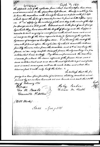
the opposite side of the cylinder from what has heretofore been done and convenient to the operators left hand. thereby enabling him to turn the machine with his right hand and feed with his left which saves the labor of a second person to feed as heretofore required. 2d in applying the revolving girth as a stay to the center of the hopper springs, and a slide girth. Bolts and nuts to the feet of said springs by which they have double the length of spring and the hopper is varied to suit any sized cars of corn with much more ease and in one quarter of the time required to do it by moving the cylinder by means of averages as heretofore done. 3d in bending the ends of the iron ribs placed upon the cylinder by which means the ribs are forcibly thrown clear from the machine, and 4th in making the frame, in an easy simple triangle form, thereby making it a firm substantial brace to itself. By these improvements the machine is made for about the same expense of the former kind and is more substantial and more durable and less liable to get out of order and is easier managed, will do the work better, and about three times as fast and with only half the labor.
In witness that the foregoing is a true specification of said corn shelling machine as improved by us we have hereunto set our hands and seals this 25th day of February 1831
Walter Parker
William M. Smith
Geo W. Banks
Granville D. Allen
(2111 Words)
Filed April 9, 1831
Published accounts: journal notice
Notice in the monthly list of patents, with remarks
Journal of the Franklin Institute, new ser., vol. 8 (1831), p. 116 · View the page
26. For a Cylinder Corn Shelling Machine; Jabez Parker and Hiram M. Smith, Richmond, Virginia, April 9.
Remarks. This shelling machine has a cylinder with ribs of iron set spirally operating round it, like the teeth in the original corn sheller. The alterations, or improvements, upon which the patentees rely, is the increasing the velocity of the cylinder three fold, by gearing, which, whilst it reverses the motion of the cylinder, enables the operator to turn the crank with his right hand, and feed the hopper with his left. The manner of fixing the springs to adapt it to ears of different sizes. The bending of the iron ribs in such a way as to throw the cobs from the machine, and the "making the frame in an easy, simple, triangular form, thereby making it a firm, substantial brace to itself." We are assured that "by those improvements the machine is made for about the same expense as the former kind; is more substantial and durable, and less liable to get out of order, is easier managed, will do the work better, and about three times as fast, with only half the labour." A gain of sixfold is a great gain, but notwithstanding this assurance we apprehend that it will be hard work even to feed with three times the ordinary speed.
About this record
- Patentee
- DATAMP
- Date
- the Name and Date index of patents, DATAMP, USPTO records
- Invention
- DATAMP
- Listed in
- the Name and Date index of patents, DATAMP, USPTO records, Jim Shaw's X-patent list, the Journal of the Franklin Institute, Burke's List of Patents (1847)
- Burke's 1847 Patent Office list gives the same patent.