

Drawings and documents
National Archives restored drawings: drawing
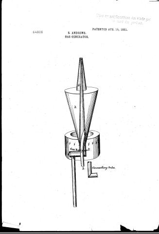
Solomon Andrew's Patent Drawing for a Gas Generator

National Archives, Restored Patent Drawings (Record Group 241) · Full-size scan at the National Archives · Catalog record
Show the text on the drawing Hide (68 words)
Words on the drawing as machine-read by the National Archives; not checked. Useful mainly for searching.
[90] Vapor Burners / $1 / Air Mixing, / Retort. / SOLOMON ANDREWS'S / GAS GENERATOR. / CLASSIFICATION / 6480-+ / Patented 15th April 1831. / DIVISION. / clored end / 4. / vahor / Boire / Val / 3. / Wr / svafer / flame / Gas Re nt / ole / oil / Connecting tube. Workinsoon / Drip / This view is larger than the Model deposited in the Patent Office ; / which model is sufficiently large for use.
USPTO scan
The patent as scanned by the USPTO
-
 Page 1
-
 Page 2
-
 Page 3
-
 Page 4
-
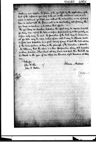 Page 5


U.S. Patent and Trademark Office · Google Patents
Show the transcription Hide (1,529 words)
Machine transcription (LightOnOCR) of the pages as scanned by the USPTO, most of them the handwritten copies made when the records were restored after the 1836 fire. Not checked; it can misread handwriting, so compare it with the scan.
Page 1.
6480X
S. ANDREWS.
GAS GENERATOR.
PATENTED APR. 15, 1831.
The specification in this page is not in print.

Page 2.
4/15/1831 6480X
April 15, 1831
Solomon Andrews, of Perth Amboy, - N. Jersey -
Letters Patent
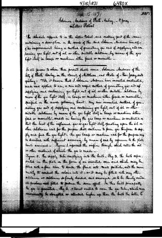
The Schedule referred to in the Letters Patent, and making part of the same, containing a description in the words of the said Solomon Andrews himself, of his improvement, being a method of generating gas, and of supplying and continuing gas light, out of oil or other suitable substance, by means of the gas light itself, in lamps or machines, either fixed or moveable —
To all persons to whom these presents shall come, Solomon Andrews, of the City of Perth Amboy, in the County of Middlesex, and State of New Jersey, salutatory greeting: Know ye, that I, Solomon Andrews, have invented, constructed, made and applied to use, a new and useful method of generating gas and of supplying and continuing gas light, out of oil or other suitable substance by means of the gas light itself, in lamps or machines, either fixed or moveable, specified in the words following, to wit: My new invented method of generating gas and of supplying and continuing gas light, out of oil or other suitable substance by means of the gas light itself in lamps or machines, either fixed or moveable, consists in having the gas lamp or machine so constructed as that the heat of the inflamed gas or gas light itself, operating upon the oil or other substance used for the purpose shall continue to form gas, therefrom to supply and feed the gas light. The gas lamp or machine used for the purpose may be described with sufficient accuracy by means of and by reference to the plates hereto annexed — Figure 1. represents the orifice through which enters the oil or other material of which the gas is made — Figure 2. The supply tube emptying into the bulb — Fig. 3. The bulb represented in the plate in the form of an inverted cone and which may be filled with a fine wire to divide the fluid into small particles, and the more readily to conduct the colonic into it; or it may be filled with any other substance or substances, so finely divided and arranged, as to be thereby rendered porous and fitted to produce the same effect. In this bulb principally the gas is generated — Fig. 4. A turret erected to cover the gas tube, which may conveniently be elongated or extended higher up than the bulb the better to
Page 3.
4/15/1831 6480X
294.
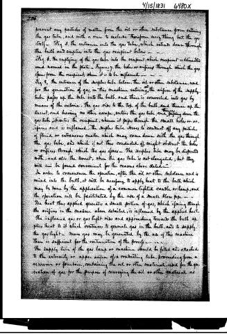
prevent any particles of matter from the oil or other substance from entering the gas tube, and with a view to exclude therefrom everything but the gas itself — Fig. 5. the entrance into the gas tube, which extends down through the bulb and empties into the gas recipient below — — Fig. 6. the emptying of the gas tube into the recipient, which recipient is delineated and named in the plate — Figures 7. the sides or orifices through which the gas issues from the recipient, when it is to be inflamed — — Fig. 8. The entrance of the surplus tube below, the oil or other substance, used for the generation of gas, in this machine entering at the orifice of the supply tube passes up the tube into the bulb, and there is converted into gas by means of the caloric. The gas rises to the top of the bulb, and thence up the turret, and having no other escape, enters the gas tube, and passing down the gas tube, enters the recipient, whence it passes through the small holes or orifices, and is inflamed. The surplus tube serves to conduct off any particles of fluid or extraneous matter which may come down with the gas through the gas tube, and which if not thus conducted off, might obstruct the holes or orifices, through which the gas issues — The surplus tube may be dispensed with, and also the turret, when the gas tube is not elongated; but they will — be found convenient for the reasons above stated —
In order to commence the operation, after the oil or other substance used is mixed into the bulb, it will be necessary to apply heat to the bulb, which may be done by the application of a common lighted candle or lamp, and the operation will be facilitated by the use of a small blow pipe — The heat thus applied generates a small portion of gas, which issuing through the orifices in the manner above detailed, is inflamed by the applied heat. The inflamed gas or gas light rises and approaching towards the bulb applies heat to it which continues to generate gas in the bulb, and to supply the gas light — More gas may be generated by the use of this machine than is sufficient for the continuation of the process — — —
The supply tube of the gas lamp or machine should be fitted and attached to the extremity or upper orifice of a conducting tube, proceeding from a reservoir or fountain, containing the oil or other material used for the generation of gas, for the purpose of conveying the oil or other material as
Page 4.
4/15/1831 6480X
297
aperture, to the orifice of the supply tube. For the more perfect operation of this machine, it will be necessary to preserve the oil or substance used for the generation of gas at a proper and regular height in the bulb, lest on the one hand, it rise so high as to enter the gas tube, or on the other, there be not sufficient in the bulb to afford a full supply of gas.
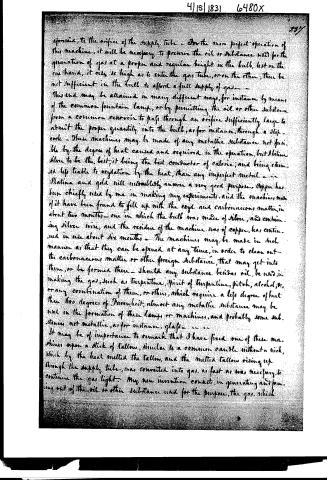
This end may be attained in many different ways, for instance by means of the common fountain lamp, or by permitting the oil or other substance from a common reservoir to pass through an orifice sufficiently large to admit the proper quantity into the bulb, as for instance, through a slip-cock. These machines may be made of any metallic substance not fusible by the degree of heat caused and required in the operation, but I believe silver to be the best, it being the best conductor of caloric, and being esteemed less liable to oxidation by the heat, than any imperfect metal. Platina and gold will undoubtedly answer a very good purpose. Copper has been chiefly used by me in making my experiments, and the machines made of it have been found to fill up with the soot and carbonaceous matter, in about two months—one in which the bulb was made of silver, and containing silver wire, and the residue of the machine was of copper, has continued in use about six months. The machines may be made in such manner as that they can be opened at any time, in order to clean out the carbonaceous matter or other foreign substance, that may get into them, or be formed there. Should any substance besides oil, be used in making the gas, such as turpentine, spirit of turpentine, pitch, alcohol, or any combination of them, or others, which require a less degree of heat than 600 degrees of Fahrenheit, almost any metallic substance may be used in the formation of these lamps or machines, and probably some substances not metallic, as for instance, glass.
It may be of importance to remark that I have fixed one of these machines upon a stick of tallow, similar to a common candle without a wick, which by the heat melted the tallow, and the melted tallow rising up through the supply tube, was converted into gas, as fast as was necessary to continue the gas light. My new invention consists, in generating and forming out of the oil or other substance used for the purpose, the gas, which
Page 5.
4/15/1831 6480X
continues, and supplies the flame of the gas light, by the application of the heat of the inflamed gas itself, to the oil or other substance used, so as to cause a continued gas light, and without the intervention or use of wick to burn in contact with the flame; and in so constructing and forming the gas lamp or machine as to produce that effect.
The gas lamp or machine to produce this effect may be varied, to wit: the gas may come out of the holes or orifices, perpendicularly or horizontally, one orifice only may be used; the formation of the bulb may be varied, several gas tubes may be used, instead of one; and it may be otherwise varied in form and proportion in a great variety of ways to suit the taste and views of the manufacturer, so long as the principle of the invention is preserved.
In testimony that the above is a true specification of my said invention as above described, I have hereto set my hand and seal this thirtieth day of March in the year of our Lord one thousand eight hundred and thirty-one.
Witnesses:
John D. Lee
John R. Watson
Solomon Andrews
[2954]
Published accounts: journal notice
Notice in the monthly list of patents
Journal of the Franklin Institute, new ser., vol. 8 (1831), p. 121 · View the page
(A description of this, and of an auxiliary patent since obtained by Dr. Andrews, will be given in the next number.) 39. For a Machine for Jointing Staves for Barrels; George Eby, Clarence, Erie county, New York, April 15.
Remarks. There are two jointers, each furnished with two plane irons, fixed by wedges in the ordinary way, but standing in opposite directions, so that they may joint a stave passing either backward or forward. These jointers are connected together her by straps of iron united by pins, which pass through holes at a distance from the jointing part of VOL. VIII.-No. 2.-AUGUST, 1831. 16 the planes, equal to that of the semi-diameter of the barrel to be formed; the faces of the planes standing in the direction of radii from these pins as centres. By means of a treadle, the faces of the jointers are made to approach each other, and joint the two sides of a stave at the same time; giving the correct bevel to the edge, whatever may be the width of the stave. The stave is attached by suitable fixtures to a jointing bar, which is made to pass backward and forward, carrying the stave between the jointers, and tilting it so as to bring it alternately in contact with the irons at each end, in order to give it the required taper. The claim is to the manner of fixing and working the jointers; the jointing bar; working and tilting as described; and the general arrangement of the machinery for producing the intended effect.
Published accounts: journal notice
Notice in the monthly list of patents, with remarks
Journal of the Franklin Institute, new ser., vol. 8 (1831), p. 188 · View the page
Remarks by the Editor.-It has been with some difficulty that we have done justice to the new orthography employed in making known the foregoing new and improved mode of curing diseases; as, however, it would have been the height of injustice to its author to have added, or abstracted, a jot or tittle from his elegant memoir, we have cheerfully undertaken the labour of following him through all his labyrinths. We are truly glad that we are not called upon to write a commentary upon the system, and still more so that we are not compelled to have its efficacy tested by becoming the patiant of this great Phesition. 1 Abstract of the specification of a patent for a method of Generating Gas, and of supplying and continuing Gas Light, out of oil, or other suitable substance, by means of the gas light itself, in lamps, or machines, either fixed or moveable. Granted to SOLOMON ANDREWS, M. D. city of Perth Amboy, Middlesex county, New Jersey, April 15,1831.
Remarks. THIS invention consists in having the gas lamp so constructed that the heat of the inflamed gas, or gas light itself, operating upon the oil or other substance used for the purpose, shall continue to form gas therefrom to supply or feed the gas light. In the accompanying drawing the letters a, a, represent a part of the supply tube through which the oil or other material enters, of which the gas is made; b, the upper end of the supply tube emptying into the bulb; c, the bulb, represented in the form of an inverted cone, which may be filled with fine wire, to communicate heat the more readily throughout the contained fluid, the gas being generated in this bulb: d, a turret erected to cover the gas tube, e, which is best elongated so as to extend above the bulb, to prevent any particles of oil or other substance from entering the gas tube. f, the entrance into the gas ANDREWS' mode of Generating Gas. tube, which descends down through the bulb into the gas recipient, g, through the holes or orifices of which the gas which is to be inflamed issues. The dots around the recipient represent these orifices, and h a waste tube to carry off any surplus oil. The oil to be decomposed enters at the orifice of the supply tube, passes up that tube into the bulb, where it is converted into gas by the heat of the flame surrounding it. The gas rises to the top of the bulb, and turret, and passes down the gas tube into the recipient, whence it issues through the openings at which it is to be lighted. The surplus tube serves to conduct off any particles of fluid which may come down with the gas, and thus prevents obstruction.
About this record
- Patentee
- DATAMP
- Date
- the Name and Date index of patents, DATAMP, USPTO records
- Invention
- DATAMP
- Listed in
- the Name and Date index of patents, DATAMP, USPTO records, Jim Shaw's X-patent list, the Journal of the Franklin Institute, Burke's List of Patents (1847)
- Burke's 1847 Patent Office list gives the same patent.