

Drawings and documents
USPTO scan
The patent as scanned by the USPTO
-
 Page 1
-
 Page 2
-
 Page 3


U.S. Patent and Trademark Office · Google Patents
Show the transcription Hide (784 words)
Machine transcription (LightOnOCR) of the pages as scanned by the USPTO, most of them the handwritten copies made when the records were restored after the 1836 fire. Not checked; it can misread handwriting, so compare it with the scan.
Page 1.
6520X
J. S. West.
Thrashing Mach.
Patented Apr. 26, 1831.
THE NORRIS PETERS CO., WASHINGTON, D. C.
Page 2.
April 26 1831 6520X 487.
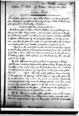
Joshua S. West of Portland, State of New York,
Letters Patent.
The schedule referred to in these Letters Patent and making part of the same containing a description in the words of the said Joshua S. West, himself of his improvement in the threshing machine,
To all to whom these presents shall come,
Be it known that J. Joshua S. West of Portland, County of Ghatangue and State of New York, having invented a new and useful improvement in the operation of threshing engines and other grain, by means of a Machine which may be applied to other purposes viz. the grinding of apples and making of Indian corn, and that the following is a full and exact description of the construction and operation of the said Machine as invented or improved by me.
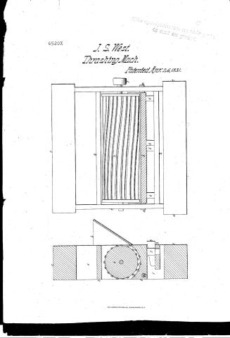
Fig. 1. 1. on the draft of the machine herewith accompanying represents two planks or pieces of timber, standing perpendicularly two or more inches thick by fourteen or more inches wide secured at each end by being tenoned into stationary square sticks of timber and the planks may stand four feet apart or more in length.
Fig. 2. 2. Represents, two pieces of plank corresponding in thickness with the above mentioned perpendicular planks or timber, the upper piece may be fourteen or more inches wide, and the lower piece ten or more inches wide and both secured at each end by being tenoned to the perpendicular planks Fig. 1. 1.
Fig. 3. Represents, a piece of timber having a concavity on the upper side corresponding with the shape and size of the cylinder Fig. 4. in which concave six or more bars of iron are imbedded longitudinally one corner of each bar being sunk the thickness of the bar which leaves one side and one edge of each bar exposed to view when not covered by the cylinder as is partly represented in this figure. The bars may be three eighths of an inch thick or more, and one and one eighth inch wide or more.
Fig. 4. Represents, a wooden cylinder fourteen or more inches in diameter at one end and thirteen and a half or more inches in diameter at the other end and gradually and regularly tapering from A. to B. the two extremities
Witnesses:
Page 3.
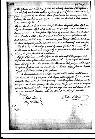
of the cylinder and small bars of iron run spirally lengthwise of the cylinder—
and are partly sunk in the cylinder by means of grooves formed in it and the bars
of iron are secured by two or more bands of iron c,c,c,c,c, running around the
cylinder, the iron bars may be similar in width and thickness to those indicated
in the concave fig. 3.
Fig. 5. Is a small block tenoned through the lower horizontal plank fig. 2, and
supports the concave fig. 3, at its center near the front edge and as the concave is
secured at each end to the plank fig. 1.1, or by a round iron near the back
side, it rolls a little when it is hard crowded by means of sticks or other
hard substance, which may accidentally pass through. When such is thrown
the lower horizontal plank, is pushed down and consequently acts as a spring
Fig. 6. 6. 6. are three keys of wood by means of which the concave fig. 3.
may be raised or lowered and consequently be graduated as to be suited to the
various purposes for which it is intended.
Fig. 7. Represents a wheel fixed on the extremity of the quidgen at the
largest end of the cylinder which connects the machine by means of a belt with the
hammer that propels it. It is intended that the iron or steel quidgen which support
the cylinder fig. 4. at each end should play in friction boxes fixed in the planks
fig. 1.1. to facilitate motion of the cylinder.
To the machine is added a hopper or feeder which receives single grain or
loose bunches, the heads of the grain at the largest extremity of the cylinder, and the
buds of the straw at the smallest extremity, so the cylinder is tapering and the
bars of iron on it run spirally, the straw passes through quartering, in consequence
of which the machine cleans itself, light and easy and does not become clogged
as is the case with machines where the straw passes through cutters.
Witnesses
Abiel Silver
Benj. H. Silver
Arthur L. West
728 n. 51
E. 4
C. J. W.
Published accounts: journal notice
Notice in the monthly list of patents, with remarks
Journal of the Franklin Institute, new ser., vol. 8 (1831), p. 171 · View the page
78. For a Thrashing Machine; Joshua S. West, Portland, Chataque county, New York, April 26.
Remarks. The "cylinder" and concave meet us, as usual, with this difference, that the cylinder is a cone, or rather, is made conical, its diameter at one end being an inch greater than at the other. Bars of iron pass from end to end of it, running spirally. "To this machine is added a hopper, or feeder, which receives English grain in loose bunches, the heads of the grain at the largest extremity of the cylinder, and the butts of the straw at the smallest extremity. As the cylinder is tapering, and the bars of iron on it run spirally, the straw passes thr through quartering, in consequence of which the machine clears itself light and easy, and does not become choked as is the case with machines where the straw passes through endwise." There is no claim made, yet certainly the whole machine is not new. The conical form of the "cylinder," we believe to be so.
About this record
- Patentee
- DATAMP
- Date
- the Name and Date index of patents, DATAMP, USPTO records
- Invention
- DATAMP
- Listed in
- the Name and Date index of patents, DATAMP, USPTO records, Jim Shaw's X-patent list, the Journal of the Franklin Institute, Burke's List of Patents (1847)
- Burke's 1847 Patent Office list gives the same patent.