

Drawings and documents
National Archives restored drawings: drawing
Warner Lafayette's Patent Drawing for a Thrashing Machine


National Archives, Restored Patent Drawings (Record Group 241) · Full-size scan at the National Archives · Catalog record
Show the text on the drawing Hide (321 words)
Words on the drawing as machine-read by the National Archives; not checked. Useful mainly for searching.
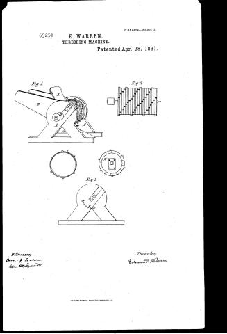
Sheet 1. 130. THRASHING. / Thrashing Machines. / A. Cylinder Machines. / 45 / Wanen's Lafayette Theashing Machine / CLASSIFICATION / Patented 28th April 1831. / 6525+ / DIVISION. / Fig. 2 / Fig.1 / Jus.3 / Description of the Traught. / Jig / Perspective view of the entire machine A The Frame / B The hopper C the Cylinder D the whirl E Guand board / Fig 3 One of the sides F holesfor the concave bars G box in which / the cyhnder hangs H Crid of the Cyhnder I one of the hoops / Fig. 2 side new of the Cylinder. / Signed in presence of us / The above is a correct represents tion qmy Safayethe Thrashing Thachine / Owen G. Warren / thorn to before me this 28.day of Feby 1838. at the city, County 2 State of Au York. / none HBD guidy / being Dead,
Sheet 2. Entered / AI / 130. THRASHING. / Thrashing Machines. / apl 28 1831 / A. Cylinder Machines. / 6525 X / CLASSIFICATION / E. Wanen's Lafayette Thrashing Machine Plate II. / 6525-X / DIVISION. / therving the method of construction when the concave is made to spring. / Fig.4 / Drig. 2 / Description of the Draught. Mig.1 One of the sides. Stig. 2 The frame seen from / the from T. The same letters refer to the same things in both figures A the two beveled pieces framed / together to form the stoly B The bed pieces C Cross bars D Hopper E The wooden springs which / support the concave F The plate of cast iron with holes in which the concave hars are set. These plates / are secured to the two end springs. G The screw at each side of the machine which regulate the Concave / This is a true represent of the modification of my Thras hung Machine / Signed in presence / Paten to 28th April 1831 In which the concave may is made to spring / Am. bewyork 9th May 1838 / Twom to before me this 9th olay of 1838- / ause G. worrer / Citycompand State of Jewyork Edwind Warren / I Marrin / P. Mitrous Commissioner afferd
USPTO scan
The patent as scanned by the USPTO
-
 Page 1
-
 Page 2
-
 Page 3
-
 Page 4


U.S. Patent and Trademark Office · Google Patents
Show the transcription Hide (597 words)
Machine transcription (LightOnOCR) of the pages as scanned by the USPTO, most of them the handwritten copies made when the records were restored after the 1836 fire. Not checked; it can misread handwriting, so compare it with the scan.
Page 1.
6525X
E. WARREN.
THRESHING MACHINE.
Patented Apr. 28, 1831.
2 Sheets—Sheet 1.
Fig. 1.
Fig. 2.
Witnesses;
E. G. Warren
S. T. Warren
Inventor;
Edmund Warren
Page 2.
6525X
E. WARREN.
THRESHING MACHINE.
Patented Apr. 28, 1831.
2 Sheets—Sheet 2.
Fig. 1
Fig. 2
Fig. 3
Witnesses;
Owen & Warren
Inventor;
Edmund Warren
THE MORRIS PETERS CO., PHOTO-LITHO., WASHINGTON, D.C.
Page 3.
6535X
April 28, 1891
Edmund Warren.
Letters Patent.
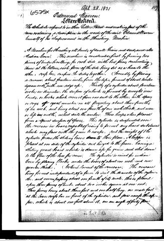
The Schedule referred to in these Letters Patent and making part of the same containing a description in the words of the said Edmund Warren himself of his Improvement in the Threshing Machine.
A Machine for threshing all kinds of small grain and seed; and also Indian Corn. This machine is constructed first by framing two pieces of timber bowling, for each side, with bed pieces connecting them at the bottom, each piece of the side being set as a brace to the other, cross bars confine the sides together. Secondly by placing a concave, about fourteen inches from the top, formed of about twelve square rods with one edge up. Thirdly of a cylinder about fourteen inches in diameter, the surface of which is formed by wrought iron bands, or hooks which cover it from one end to the other, with spurs or cogs of equal number on all projecting about three-fourths of an inch, and being about one-fourth of an inch thick, and one or half inch wide, as best suits the work. These hooks when placed form a spiral surface of spurs. This cylinder is suspended over the concave in boxes capable of rising to permit any hard substances which may pass with the grain to escape, and the weight of the cylinder forces the sliding boxes down to their place. A hopper is placed at one side of the cylinder and hinged to the frame, having a sliding guard board which is drawn up for grain, and slid down to the floor of the box for corn. The cylinder is raised for Indian Corn by placing blocks under the boxes of about one inch and one quarter thick. Section Second of the concave. The concave being formed independent of a form to suit the diameter of the cylinder, and encompassing about one-fourth of its circle, this is placed upon three pieces of timber about two inches square at one end, these pieces being about three feet and one-half long, are made fast at the lower cross bar in front of the cylinder, and from across the hopper, which is about one foot above it, on an angle of forty five degrees.
in Test 1891
Page 4.
6555x
Apr 28, 1831
degrees, which places the concave under the cylinder, and it is raised or lowered by screws at the second cylinder. In this section the cylinder may be made fast without sliding boxes. The cylinder is put in motion by a band attached to a wheel, on one end of the cylinder and driven by any power sufficient; the length of the cylinder for two horse power is about two feet, for one horse power eighteen inches is sufficient. I claim in this, the wrought iron hooped cylinder with springs, the particular form of the frame to give great strength with little expense, or workmanship, as also the inclined springs for the concave, with the mode of changing them by screws for corn.
Edward Warren
Witneses
Honey Darrig
Sam Clark
(Patented April 28, 1831) (559 words)
Published accounts: journal notice
Notice in the monthly list of patents, with remarks
Journal of the Franklin Institute, new ser., vol. 8 (1831), p. 172 · View the page
80. For a Thrashing Machine; Edmund Warren, city of New York, April 27.
Remarks. The cylinder is to be banded with iron from end to end, and is to have teeth; the concave is to be like other concaves; the frame supporting the cylinder is in the form of an equilateral triangle, resting on one of its sides; the claim is to "the wrought iron hooped cylinder with spurs; the particular form of the frame, to give great strength with little expense or workmanship; as also the inclined springs for the concave, with the mode of changing them by screws, for corn."
About this record
- Patentee
- DATAMP
- Date
- the Name and Date index of patents, DATAMP, USPTO records
- Invention
- DATAMP
- Listed in
- the Name and Date index of patents, DATAMP, USPTO records, Jim Shaw's X-patent list, the Journal of the Franklin Institute, Burke's List of Patents (1847)
- The National Archives' catalog gives the name differently.
- The Franklin Institute's journal gives a different date.
- Burke's 1847 Patent Office list gives the same patent.
- Burke's 1847 Patent Office list gives a slightly different date; the date shown follows the standard lists.