

Drawings and documents
National Archives restored drawings: drawing
Reuben Meriam's Patent Drawing for an Improvement in the Cut, Prick, Set Machine

National Archives, Restored Patent Drawings (Record Group 241) · Full-size scan at the National Archives · Catalog record
Show the text on the drawing Hide (53 words)
Words on the drawing as machine-read by the National Archives; not checked. Useful mainly for searching.
104, WIRE WORKING. / Wiring, / Brushes & Cards. / $3 / TREUBEN MERIAM'S / (no number) / Improve ment in the Cut,Prick,s Set, Macbine / CLASSIFICATION / 6533-4 / DIVISION. / Patented 2d May 1831g / el / drives A / should on Muttemore / OIR / G S Del
USPTO scan
The patent as scanned by the USPTO
-
 Page 1
-
 Page 2
-
 Page 3
-
 Page 4


U.S. Patent and Trademark Office · Google Patents
Show the transcription Hide (939 words)
Machine transcription (LightOnOCR) of the pages as scanned by the USPTO, most of them the handwritten copies made when the records were restored after the 1836 fire. Not checked; it can misread handwriting, so compare it with the scan.
Page 1.
6533X
R. Meriam.
Card-Setting Machine.
Patented May 2, 1831.
Page 2.
May 2, 1831
6533X
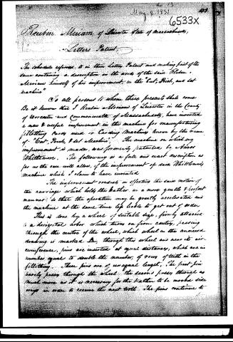
Reuben Meriam, of Leicester, State of Massachusetts,
Letters Patent
The schedule referred to in their Letters Patent and making part of the same containing a description in the words of the said Reuben Meriam himself of his improvement, in the "Cut, Pick, and Set Machine"
To all persons to whom these presents shall come
Be it known that I Reuben Meriam of Leicester in the County of Worcester and Commonwealth of Massachusetts, have invented a new & useful improvement in the machine for manufacturing Filleting Cards used in Carding Machines known by the name of "Cut, Pick, & Set Machine". The machine on which my improvement is made, was formerly patented by Aaron Whittemore. The following is a full and exact description as far as the case will allow, of the improvement of said Whittemore's machine which I claim to have invented.
The improvement consists in effecting the said motion of the carriage which holds the kather in a more gentle & perfect manner, so that the operation may be greatly accelerated and the machine at the same time less liable to get out of order.
This is done by a wheel of suitable size, firmly attached to a horizontal arbor which turns on firm center, passing through the center of the wheel, which wheel in the annexed drawing is marked D, through this wheel and near its circumference, pins are inserted at equal distances, which are in number equal to double the number of rows of teeth in the filleting. These pins are of unequal length. The first pin barely passes through the wheel, the second passes through as much more as it is necessary for the kather to be moved side ways in order to receive the next tooth. The pins continue to
Page 3.
to lay them in the same proportion half round the wheel, and then are shortened in the same proportion on the other half of the wheel to the pins first mentioned, except that there are two long pins of the same length, standing together, and two short pins of the same length standing together, at the longest and shortest ends.
The above-mentioned wheel is put in motion by another wheel marked B, in the annexed drawing which is firmly attached to an arbor turning with equal speed with the main arbor of the machine, on the outer edge or circumference of the last-mentioned wheel are a suitable number of teeth placed in the form and operating in the manner of an endless screw, which take hold of the cog wheel, marked C, in the drawing, which cog wheel is attached to the arbor passing through the wheel A.
These teeth pass about half round the wheel in the annexed drawing, on the other half of the circumference of the wheel is a groove, which holds the wheel B in its proper place while the card tooth is inserted. The ends of the pins inserted in the wheel marked A pass against a plain placed perpendicularly nearly in the form of a segment of a circle, which is marked in the annexed drawing D, in the centre of this plain the operating pin becomes stationary when it is necessary for the carriage to be so, the upper part only of the plain appears in the drawing, the plain is kept close to the pins, by a spring or weight suspended by a cord fastened to the carriage and passing over a loose pulley, thus by half the revolution of the wheel A the teeth are set once across the card from left to right, and by the other half of the revolution, another row of teeth is set from right to left.
The plain is attached to a slide in the carriage marked E in the drawing it is flat and moveable and within a short distance, on the back side of the slide not seen in the drawing is a small wheel attached to an arbor and turned in centre firmly attached to the carriage, through which wheel are inserted a sufficient number of small pins the
Page 4.
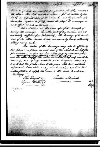
the ends of which are made to leap, against another plain attached to the slide. The last mentioned wheel is put in motion by two levers on opposite sides of the wheel A, and the operation of its lever pins against its plain, moves the plain D, sideways, so as to effect at will in the card.
What I claim as the above specified principle of moving the carriage. The other parts of my machine are not materially different from Whittemore's. The carriage of his machine and of all others, known to me, are moved by hands, alternately sitting into a rack.
The motion of the carriage may also be effected by two plains; one placed on each side of the wheel A and half of the pins reversed, so that one half shall leap against one plain and the other half of the above described plain only would be necessary, and springs must be made to operate alternately so as to keep the plains close to the pins. This last mentioned improvement I also claim as my own invention, and have it in contemplation to apply the same to the said machine.
Witnesses
John Sargent
Lyman Wister
Reuben Allerman
Published accounts: journal notice
Notice in the monthly list of patents, with remarks
Journal of the Franklin Institute, new ser., vol. 8 (1831), p. 175 · View the page
1. For improvements on a machine formerly patented by Amos Whittemore, for Cutting the Teeth, Pricking the Holes, and Setting the Teeth in Filleting Cards; Reuben Meriam, Leicester, Worcester county, Massachusetts, May 2.
Remarks. "The improvement consists in effecting the side motion of the carriage which holds the leather, in a more gentle and perfect manner, so that the operation may be greatly accelerated, and the machine at the same time be less liable to get out of order." How this is to be accomplished we shall not attempt to describe, the complexity of the machine rendering any such attempt useless, excepting to those few who are perfectly acquainted with the structure of this ingenious instrument, as at present made.
About this record
- Patentee
- DATAMP
- Date
- the Name and Date index of patents, DATAMP, USPTO records
- Invention
- DATAMP
- Listed in
- the Name and Date index of patents, DATAMP, USPTO records, Jim Shaw's X-patent list, the Journal of the Franklin Institute, Burke's List of Patents (1847)
- Burke's 1847 Patent Office list gives the same patent.