

Drawings and documents
National Archives restored drawings: drawing
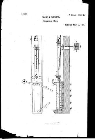
T. Evans and J. Parsons' Patent Drawing for a Suspension Dock


National Archives, Restored Patent Drawings (Record Group 241) · Full-size scan at the National Archives · Catalog record
Show the text on the drawing Hide (176 words)
Words on the drawing as machine-read by the National Archives; not checked. Useful mainly for searching.
Sheet 1. $40 / 1. MYDRAULIC ENGINEERING / T I ovans &J. Parsons. / Vol.13.p.129. / DecksiLifing / Dock / Patented 13th May May 1831, / CLASSIFICATION / 6552-+ / DIVISION. / Fid.1. / Patent office 30 lept 1841, / Made under the docution of the Commision I Petents / in couf onnity with act of bougrep 3 March 1837,
Sheet 2. 129 / HYDRAULIC ENGINEERING / CLASSIFIC Docksil ifting / 6552-+ / DIVISION. / KLKLKLKLKL / References. Fig.1. Perspective view, Fid.2, toprew of one of the / drawing frames. Fig 3 birtical section drawing frame / A.A. line of the thore B,B, wharves projecting atter intangly / from A, drawing frames D cradle E cast iron "Roach whals" / Epalls. a, cradle chains, H. friction wherls. I. Plate timber, / K. funing pieus Is "fins." M. aylinders N.bolts by which cylinders / are fashernd to the plate. Opiston. Prod. Q. / forming water into the cylinder worke day steam Engine / R.pipes for descharging water from one cylinder to another, / S. serio for drawny up chain Ifemale screw. u endlep screw, / Vanother mode of shortining the chain,
USPTO scan
The patent as scanned by the USPTO
-
 Page 1
-
 Page 2
-
 Page 3
-
 Page 4
-
 Page 5
-
 Page 6
-
 Page 7
-
 Page 8


U.S. Patent and Trademark Office · Google Patents
Show the transcription Hide (2,343 words)
Machine transcription (LightOnOCR) of the pages as scanned by the USPTO, most of them the handwritten copies made when the records were restored after the 1836 fire. Not checked; it can misread handwriting, so compare it with the scan.
Page 1.
6552X
EVANS & PARSONS.
Suspension Dock.
2 Sheets—Sheet 1.
Patented May 13, 1831.
Fig. 1
N. PETERS, Photo-Lithographer, Washington, D. C.
Page 2.
6552X
EVANS & PARSONS.
Suspension Dock.
2 Sheets—Sheet 2.
Patented May 13, 1831.
N. PETERS, Photo-Lithographer, Washington, D.C.
Page 3.
6552x May 13, 1851 129
Thomas Evans and John Parsons, of New York City
Letters Patent
The Schedule referred to in the Letters Patent and making part of the same containing a description in the words of the said Thomas Evans and John Parsons, themselves, of their improvement in the apparatus for lifting ships and other vessels called the Hydrastatic suspension Dock.
To all whom these presents shall come. We do know that we Thomas Evans (machinist) and John Parsons (ship carpenter) of the City and State of New York, have invented, made and applied to use a new and useful improvement in the art of lifting ships and other vessels, for inspection and repairs, called Evans and Parsons Hydrastatic suspension Dock, and that the following is a full and exact description thereof, to wit, Two piers, wharfs, or other suitable structures are formed at right angles to the shore or current of the River, by driving piles in the bed thereof, in precisely the same manner as such piers have been constructed before, for new docks and other constructions when the ships are lifted vertically out of the water. If we suppose this dock to be capable of raising a ship of six hundred tons, it should be one hundred and twenty feet in length and thirty-six in width between the piers, having a clear lift of fourteen feet, this being a convenient size for vessels of that class, but it is evident that the dimensions of the docks must vary to suit the craft raised thereon. The piles forming the inner rows in each side of the piers or dock being driven with great care and at an equal distance around as possible, are secured together at the level of the piers by two large and solid pieces of oak timber, called plates, running the whole length of the dock including the head thereof at the land ends. The use of this extension will be shown hereafter. In the dock we have supposed the inner rows of piles would be eight feet apart in the other lengthwise of the dock into the aforementioned plates which rest on and are firmly secured to the piles last mentioned. Bearings are made to receive large cast iron board wheels, respectively having ample fastenings to
Drawing
Page 4.
support them (the wheels) that they may be fully on their bearings. These wheels may be about two feet wide, made thin to one end, and are so arranged that the propelling shall be exactly in the centre between each pair of piles, the rotation being lengthwise of the dock. The edge or rim of the roach wheels may in some cases be simply a shallow groove like a sheave of a block, excepting it is made to receive a toggle chain instead of a rope. In case the wheels are made in this manner, the falls that are intended to prevent accidents would be made to fall into the chain, when the ship is in the act of raising out of the water. On the other hand, if it should be deemed advisable to fall the wheels instead of the chains, then the wheels should be made with teeth of such a form as will insure their passing in and out freely from the openings of the toggle chains, without catching. A portion of the edge of the wheels being notched to receive two falls on each side, the teeth of the wheels prevent the chains from slipping when the machine is at rest. Cradle beams are provided similar to those used for lifting ships in a variety of ways, the construction of which are so well understood that they need not be described. The length of these beams are governed by the size of the dock. Two of these beams form a section, they are kept about two feet apart and are planted from one to the other on the inner side, the space being filled with ballast to make the cradle solid. Strong chains pass down over the aforesaid roach wheel, and are strongly fastened to the beams forming the cradle, one chain on each side sustaining a section. The other ends of the chains are fastened to two pieces of iron placed directly over the plates and fastened therewith anchoring from the lower end of the dock to the wharf. These pieces are called the drawing frames. There are two drawing frames, one on each pier, over their respective plates. These frames are firmly held at a sufficient distance apart to allow the roach wheels and chains room to come between without touching. These frames have a horizontal motion of whatever vertical lift is required to raise the ship. The drawing frames are guided in their passage back and forward by friction wheels having flanges to them, on which they likewise move.
Page 5.
the chains afterwards coming up from the beams through the plate, and passing over the roach wheels, as far as their centre, are fastened to the drawing frames in a particular manner, of which more hereafter. At the land end of the stock and directly in a line with the drawing frames are placed two cylinders, one over each plate on either side of the stock. The extension of which portion of the beginning is for the purpose of better securing the cylinders in their places, which is accomplished by bolting pieces of timber called furring timbers to the plate. The thickness of these pieces being such that the top faces are in a line with the centre of the cylinders, which having projections cast on each side called fins of sufficient breadth and thickness, likewise having other fins running at right angles to the body of the cylinders on the underside of the first mentioned fins, these last are let into the furring timbers their whole width, say three inches. Bolts being now passed through the longitudinal furring timbers, and plates are firmly thereby secured to the stock. These cylinders are intended to act as hydraulic presses, the pistons being drawn inwards in the operation of lifting. They consequently must have a piston similar to a steam engine with a rod passing through a stuffing box: this rod must be of sufficient size to haul up one half the united weights of the ship and cradle. The space between the heads of the cylinders and the ends of the drawing frames, when the cradle is sunk to its greatest depth must always be somewhat greater than the distance the ship is to be elevated. A steam engine is to be placed in a convenient situation as possible to which will be attached two pumps, for forcing water into the cylinders. There must always be two pumps, one to each cylinder, and there must never be any communication between these pumps, or the pipes leading from them to the cylinders, for reasons given hereafter. We will now suppose in respect to be floated in between the plates and moved in a proper position to be raised. The pistons being over out their whole length, they are each strongly attached to the afore said drawing frames. The pumps being put in operation the pistons of the hydraulics are drawn in to their respective cylinders. The chains to which the cradle is suspended being fastened to the drawing frames, the vertical motion of the ship and cradle is converted into a horizontal one by the chains passing over the afore said Roach wheels, it is evident of the pistons continue to
Page 6.
132 6552x May 13, 1831
needs the ship will be drawn up as long as that motion continues. The vessel being now completely lifted out of the water, the pumps being stopped the weight of the ship is sustained by the aforesaid falls, on the scow wheels, they likewise form a perfect security against accidents while the ship is lifting the hydraulics with their respective pumps must be as near equal as possible or the ship will be farther advanced on one side than the other there being no communication between the cylinders. If the pumps are equal in their boxes and length of stroke both sides of the cradle must come up level no matter how unequal the load may be.
The operation of lowering the ship is quite a different work. The friction of the machinery and weight of the cradle being so unequal, that in attempting to let down a ship by opening two orifices of equal diameters in each Hydraulics the side which moved easiest kept gaining rapidly on the other by the weight of the ship being thrown on that side until utter destruction ensued. To correct this evil and which the Patentees consider a most important feature in their invention, is what we term a self-regulating apparatus. This consists in the insertion of a pipe into the head of each cylinder, each of these pipes passing in a diagonal manner to the back end of the other cylinder, each of these pipes have a stop cock in them for shutting off the communication when the ship is lifting there are likewise two discharging cocks, the use of which is to let the water out of the cylinder when necessary. Now let us suppose a ship ready to be let down, the pistons are forced back sufficient to relieve the falls on the scow wheels, the stop cocks first mentioned in the diagonal pipes are opened, the water in either cylinder being all forced of the pistons is acted on by the weight of the ship cause it to escape with great force, but it is shown that the water does not escape into the atmosphere, but is conveyed from before one piston to the rear of the other they produce a most perfect equilibrium in the descent of the ship, for if one piston be drawn by fifty tons more than the other, it cannot move an inch, till the other moves also, because if the second piston remains at rest the first has no place to discharge its water, therefore whatever power the first piston has over the second it exerts just as much to it they therefore move together. This was confirmed by actual
Page 7.
6552x
May 13, 1831
130
experiments, when the ships afloat, the cylinders are as full of water as ever it being merely conveyed from one cylinder to the other, when the next operation takes place, the discharging cocks are opened to let the water escape.
In repairing a ship's bottom it is often necessary to lower a section without disturbing the rest, one method to do this is to attach screws to the end of each chain, the female being made to stand in such a position between the drawing frames as to be nearly horizontal, the female screws would have a sufficient support to revolve against, having spiral teeth on their peripheries, an endless screw being made to work into these teeth, a power is gained for lowering and hoisting the sections. Another method is to place Iron Rollers on the drawing frames in proper places, and simply winding a portion of each chain round the roller wheels, and endless screws may be attached to the rollers, thereby they may be wound, or unwound conveniently.
Another great use of these separate powers on the sections are to adapt the shape of the Krogged head of the ships. This is one of the greatest advantages the ordinary lift docks have in common over all species of inland planes, it is intended as all the machinery attached to the chains, whether screws or rollers are fixed in exactly the same position between the drawing frames, we propose that to save expense instead of having sufficient gearing attached to each chain to work it, that we just have each chain with a roller or screw, wherever is used, furnished so far as the first motion, then if we have a frame with wheels attached to it, these wheels to have flanges and one on the top of the drawing frames similar to a flat boat carriage, this frame containing the requisite powers for working section may be run along from one chain to the other, and will answer for the whole.
What we claim as new and our invention, to avoid confusion we will state under distinct heads.
First. We claim the invention or application of placing the Hydrostatics or cylinders in a horizontal position whereby we are enabled to make 2 cylinders answer, and therefore have the advantage of applying the moving power at one point.
Second. We claim the invention of the self-regulating apparatus as described above taken in connexion with the Hydrostatics for the purpose of lowering the ships.
Third. We claim the drawing frames with their appendages viz. the chains and anchor wheels as we have applied them to
Page 8.
134 6552x May 13, 1831
a vertical lift dock for repairing ships and other vessels. A glider has been placed in a horizontal position before for a variety of purposes, roach wheels and chains for hauling up ships on inclined planes, even in cases of sudden vessels, chains have been used to lift them vertically. This being the case, we thought best to promise that we claim the above mentioned machinery only as we have combined them together in a fixed stationary machine (called a vertical lift Dock) and it is the relative position and combined operation of the parts that forms the novelty of our claims.
Test: Witnesses
Mfg. P. Mc Cormay
C. De Bann
J. Beams
John & Parsons.
(2,750 words)
(Granted May 13, 1831)
Published accounts: journal notice
Notice in the monthly list of patents, with remarks
Journal of the Franklin Institute, new ser., vol. 8 (1831), p. 179 · View the page
21. For Machinery for lifting Ships out of Water, for inspection and repair; Thomas Evans, machinist, and John Parsons, ship carpenter, city of New York, May 13.
Remarks. This apparatus is intended to lift ships vertically out of the water, in the manner of the screw docks; but the power applied is that of the hydrostatic press. Its mode of application, however, differs essentially from that of Thos. Evans, described at p. 160, vol. 6. Two cylinders, furnished with pistons, are placed horizontally, one at each side of the dock, at the land end. A steam engine is employed to force water into the cylinders, to depress the pistons. To the piston rods, timbers, forming a sliding frame, are attached, which extend along the sides of the dock, and from these timbers chains pass over pullies, and act upon other timbers crossing the dock, and over which the vessel is to be floated, as in the screw docks. There is an ingenious but simple contrivance for letting the vessel down, after her repairs have been completed; this we shall not at present attempt to describe, as it is our design hereafter to give an abstract of the specification, accompanied by engravings.
About this record
- Patentee
- DATAMP
- Date
- DATAMP, USPTO records, Burke's List of Patents (1847)
- Invention
- DATAMP
- Listed in
- the Name and Date index of patents, DATAMP, USPTO records, Jim Shaw's X-patent list, the Journal of the Franklin Institute, Burke's List of Patents (1847)
- The sources give different dates; the date shown is the one most of them agree on.
- The Franklin Institute's journal confirms the date shown.
- Burke's 1847 Patent Office list gives the same patent.