

Drawings and documents
National Archives restored drawings: drawing
W. Bryant and I. Heyett's Patent Drawing for a Railway Carriage

National Archives, Restored Patent Drawings (Record Group 241) · Full-size scan at the National Archives · Catalog record
Show the text on the drawing Hide (102 words)
Words on the drawing as machine-read by the National Archives; not checked. Useful mainly for searching.
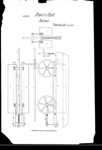
104 rallways, / 02 / 120, / Elevated / Wo BRYANT EI. O HYETT / Railway Carriage / Patinted June/13"1831. / Pale, / CLA ATION / 6562 / [120] Ways / 1. "The Way " / DIV ISI ON / 104. RAILWAYS. / A Wheels / B. Principal Rail / C Wheel Prame / D. Re Rodsol Iron supi / FOS / E: Guards / P. Body of Carray / a Bar forning axiso / H Secondary Rail ..A / I. Benl perced Iron / Fat / FOR / K GuideWheets / L. Guide Rest / M Rod keping WR / Ta / Strickland Del / Made Made under the desection of the / in conformity with ach of 3 March / L Sthoor / Com
USPTO scan
The patent as scanned by the USPTO
-
 Page 1
-
 Page 2
-
 Page 3
-
 Page 4
-
 Page 5


U.S. Patent and Trademark Office · Google Patents
Show the transcription Hide (1,102 words)
Machine transcription (LightOnOCR) of the pages as scanned by the USPTO, most of them the handwritten copies made when the records were restored after the 1836 fire. Not checked; it can misread handwriting, so compare it with the scan.
Page 1.
6562X
Bryant & Hyett.
Railroad.
Patented Jun. 13, 1881.
THE GRAPHIC CO. PHOTO-LITH. 39 & 41 PARK PLACE, N.Y.
Page 2.
June 13, 1831
William Bryant & Isaac Hiatt.
Letters Patent.
The Schedule referred to in these Letters Patent, and making part of the same, containing a description in the words of the said William Bryant and Isaac Hiatt, as themselves, of their improvement in the rail-way carriage.
To all whom these presents shall come,
Be it known that we William Bryant and Isaac Hiatt, of the County of Davidson and State of Tennessee, have invented a new and useful carriage, to run on such Rail-ways as have but one principal rail to bear the chief weight of the carriage and load, and a secondary rail to steady the carriage; and that the following is a full and exact description of our said invention.
The plan of the before named carriage is as follows:
Two wheels of about three feet in diameter, three inches wide on the rim, and six feet apart, from centre to centre, run on the principal rail. The wheel frame, consists of two bars of wood or iron, of strength in proportion to the weight to be conveyed; placed one on each side of the principal rail, they extend from a few inches back of the axle of the hind wheel forward about two feet in front of the fore wheel. These bars are framed together about one foot apart, and are suspended from the axles of the wheels by four rods of iron, which are attached to the bars at their lower ends, and at their upper ends to the boxes in which the axles run.
The bottom of the bars are about one inch and a half below the surface of the rail; to their under sides opposite each wheel are attached short pieces of wood or iron termed guides.
Page 3.
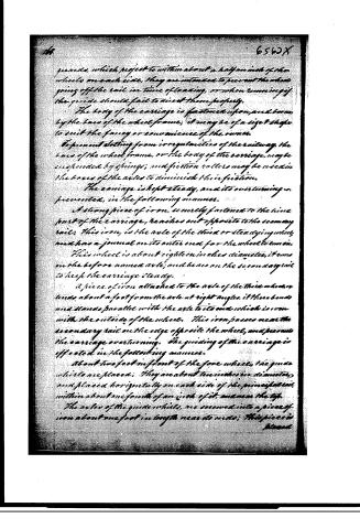
guards, which project to within about a half an inch of the wheels on each side, they are intended to prevent the wheels going off the rail, in time of loading, or when running if the guide should fail to direct them properly.
The body of the carriage is fastened upon, and borne by the bars of the wheel frame; it may be of a size or shape to suit the fancy or convenience of the owner.
To prevent clattering from irregularities of the railway, the bars of the wheel frame, or the body of the carriage, may be suspended by springs; and friction rollers may be used in the boxes of the axles to diminish their friction.
The carriage is kept steady, and its overturning is prevented, in the following manner.
A strong piece of iron, securely fastened to the hind part of the carriage, reaches out opposite to the secondary rail; this iron, is the axle of the third or steadying wheel, and has a journal on its outer end for the wheel to run on.
This wheel is about eighteen inches diameter, it runs on the before named axle; and bears on the secondary rail to keep the carriage steady.
A piece of iron attached to the axle of the third wheel, extends about a foot from the axle at right angles, it then bends and stands parallel with the axle to its end which is iron with the outside of the wheel. This iron passes near the secondary rail on the edge opposite the wheel, and prevents the carriage overturning. The guiding of the carriage is effected in the following manner.
About two feet in front of the fore wheel, the guide wheels are placed; they are about ten inches in diameter, and placed horizontally on each side of the principal rail, within about one fourth of an inch of it, and near the top.
The axles of the guide wheels, are screwed into a piece of iron about one foot in length near its ends; this piece is placed
Page 4.
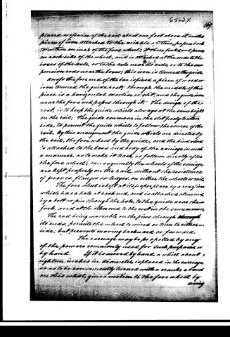
placed on the inside of the rail about one foot above it, another piece of iron attached to the middle of this, projects back to within an inch of the fore wheel; it has forks, and passes on each side of the wheel, and is attached at the ends to the boxes of the axle, or to the axle near its ends, or to the suspension rods near the boxes; this iron is termed the guide.
And so the fore end of the bar is fixed a piece of wood or iron termed the guide rest; through the middle of this piece is a horizontal mortise or slit, and the guide iron near the fore end passes through it. The design of the rest, is to keep the guide wheels always at the same height on the rail; the guide can move in the slit freely to either side, to permit the guide wheels to follow the course of the rail. By this arrangement the guide wheels are directed by the rail, the fore wheel by the guide, and the hind wheel is attached to the bars and body of the carriage in such a manner, as to make it lead, or follow, directly after the fore wheel; consequently the wheels of the carriage are kept properly on the rail, without the assistance of grooves, flanges or ledges, on either the wheels or rail.
The fore wheel is kept at its proper place by a rod of iron which has a hole at each end, and is attached at one end, by a bolt or pin through the hole, to the guide near the fork, and at the other end to the rest in the same manner.
The rod being movable on the pins through its ends, permits the wheel to wind or turn to either side; but prevents moving backwards or forwards.
The carriage may be propelled by any of the powers commonly used for such purposes, or by hand. If it is moved by hand, a wheel about eighteen inches in diameter, is placed in the carriage so as to be conveniently turned with a crank, a band on this wheel, gives motion to the fore wheel by means
Page 5.
Driving a whistle on its axle of about six inches diameter; or instead of the whistle and bands before named, bag wheels may be used.
Witnesses
Mrs. Carroll
Alas Porter
Mr. Bryant
Isaac Veille
1078 nts
Published accounts: journal notice
Notice in the monthly list of patents, with remarks
Journal of the Franklin Institute, new ser., vol. 8 (1831), p. 250 · View the page
3. For a Carriage to run on Rail-ways; William Bryant, and Isaac Keit, Davidson county, Tennessee, June 13.
Remarks. This carriage is intended to run upon a single rail, in a manner resembling that of Palmer's, patented in England. The carriage is suspended so as to hang below the rail upon which the wheel runs. From the frame by which gudgeons of the main wheel are sustained, an arm projects, upon which there are wheels, or friction rollers, which acting upon the top, and on each side of the rail, serves to guide the carriage, and renders it unnecessary to use flanches. The whole apparatus is described and figured without any part being designated as new, although it is manifest that the principle has no claim to novelty. The particular arrangement of the parts described, differs sufficiently from that adopted by Palmer to have admitted of a specific claim. Notwithstanding the apparent simplicity of the single rail, its employment involves a complexity in the adaptation of the carriage, and in other particulars which appear to be objectionable. We believe that Palmer's rail and carriage have been used for the purpose of experiment only; at all events, we have never heard of any thing further respecting them, although they were patented three or four years ago. To sustain a rail at the height required by this plan, with that degree of stability which is necessary, offers such practical difficulties as are very likely to prevent its adoption.
About this record
- Patentee
- DATAMP
- Date
- the Name and Date index of patents, DATAMP, USPTO records
- Invention
- DATAMP
- Listed in
- the Name and Date index of patents, DATAMP, USPTO records, Jim Shaw's X-patent list, the Journal of the Franklin Institute, Burke's List of Patents (1847)
- Burke's 1847 Patent Office list gives the same patent.