

Drawings and documents
National Archives restored drawings: drawing
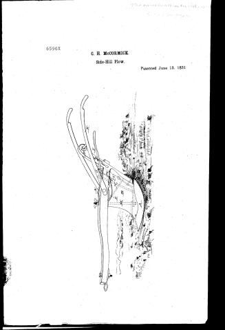
Cyrus H. McCormick's Patent Drawing for a Hill Side Plough

National Archives, Restored Patent Drawings (Record Group 241) · Full-size scan at the National Archives · Catalog record
Show the text on the drawing Hide (85 words)
Words on the drawing as machine-read by the National Archives; not checked. Useful mainly for searching.
Eintered / nill. / CLASSIFICATION / 6596X / DIV ISION. / CYRUS H M°CORMICK / Hill Side Plough Model not restored? / Patented June 13. 1831. / H.H The share годз I K Spring J Julerum L Bivot-rod / A share B The mouldboard References C The brace D Beam E Handes F Standard G Lower brace har / CANADA / Patent office 12 Jan / Made under the direction of the Commipu / of Patents in conformity with act 3 Me / 9,801 / Merry / Knot Restored
USPTO scan
The patent as scanned by the USPTO
-
 Page 1
-
 Page 2
-
 Page 3
-
 Page 4


U.S. Patent and Trademark Office · Google Patents
Show the transcription Hide (1,064 words)
Machine transcription (LightOnOCR) of the pages as scanned by the USPTO, most of them the handwritten copies made when the records were restored after the 1836 fire. Not checked; it can misread handwriting, so compare it with the scan.
Page 1.
6596X
C. H. McCORMICK.
Side-Hill Plow.
Patented June 13, 1831.
Page 2.
June 13, 1851
Cypres H. Mc Cormick
Letters Patent
The enclosed reference to in these Letters Patent and making part of the same containing a description in the words of the said Cypres H. Mc Cormick himself of his improvement in the Hill Side Plough.
It is known that Cypres H. Mc Cormick of Rockbridge County State of Virginia have made an improvement in the Hill Side Plough which is described as follows. This plough consists of the following parts: 1st The share & the mould board with its brace & the beam, handles, & standers or hinder supports. 4th The lower brace bar. 5th The locking rod & lever. 6th The fulcrum & spring. 7th The brace rod. 8th The pivot rod & screw. 11th The share. The share is made double of iron & steel with a point at each end and a double spring on the same side at each end of the share, at the distance of the point of the mould board is a pin against which the mould board locks and is kept in its place. At a proper distance from the points of the share are two holes one at each end to receive the rods to be hereafter described.
2nd The mould board with its brace. The mould board is made double with a brace extending between the wings & supporting share. This which brace has two holes one near each end to receive a pin or locking rod to be hereafter described. Near the front and quite thru the mould board is a hole thru which a pin or rod is to pass to be also hereafter described.
3rd The beam handles & standers or hinder supports. The beam handles are made in the usual form & of a suitable size and strength. A hole is made thru the beam to receive the pivot rod. The standers or hinder support is made of any convenient size it is placed at the end of the beam and has a hole mortise in it to receive the tenon of the beam, also a mortise thru which a brace passes to support the handles. At the lower end of it is fixed the lower brace bar to be next described.
4th The lower brace bar. This is made of iron and extends from the lower end of the hinder support, to about the middle of the share and has an eye.
Page 3.
opening in it to let the pivot rod pass thro' & is made fast to the standard or hinder support. There is also another hole near the middle of the bar thro' which the locking rod passes into the share. 5th The locking rod & Lever. The long locking rod passes down thro' the beam thro' the lower brace bar into the share having a shoulder on the upper side of the bar to prevent its going too far, and another shoulder or projection even with the upper side of the beam, to be operated on by a spring to be hereafter described. This rod also has an opening made in the spring and has a hook or screw at the upper end to attach it to the lever. Another locking rod is riveted to the spring & passes thro' the beam and the holes made near each end of the brace bar of the mould board. The lever is made of any convenient length & moves on a fulcrum placed beside the spring & is attached to the first mentioned locking rod. There is a pin or projection on the standard or hinder support to hold it to its place whilst turning the plough. 6th The fulcrum & spring. A piece of iron forming the fulcrum fastened to the beam and rising two or three inches above the spring, on the top of which is placed the lever. The spring is made of iron or steel and is fastened to the beam. At proper distances, openings are made to let the pivot rod and long locking rod pass. The other locking rod as mentioned before is riveted to this spring. 7th The brace rod passes thro' the standard or hinder support to the beam near where it is connected with the mould board. There is a hole thro' one end of this rod, thro' which the pivot rod passes, the other end passes thro' the standard or hinder support & lower brace bar & is fastened with a screw. 8th The pivot rod & lever. The pivot rod is made of iron & passes thro' the share, the lower brace bar, mould board, beam & spring & is fastened with a nut on the top. Operation. When it is required to turn the furrows all one way, the first furrow being run, the lever is pressed down and fastened by the pin on the side of the standard or hinder support, by which the long locking rod is drawn out of the share, the upper shoulder of which acts upon the spring and consequently draws the other locking pin out of the mould board.
Page 4.
board brace; all being now loose, the plough is turned, the share remaining stationary and the mould board turned till stopped by the pin in the share; which produces the required change in the plough, so as to throw the next furrow the same as the first. Then disengaging the brace, the spring operates on both the locking rods to fasten both the mould board & share together and the ploughing is recommenced. This plough can also be used as a common plough. What (classic words) invention is the combination and arrangement of the different parts of the above described plough so as to effect the turning and securing the mould board, and other parts of the plough to the share but particularly in making the mould board to turn whilst the share remains stationary and afterwards locking it to the share, together with an improvement in the construction of the share.
Witnesses
Aaron P. Elliot
L. Warren Fuggles
Cypus H. McConnick
Filed June 13, 1831
Published accounts: journal notice
Notice in the monthly list of patents, with remarks
Journal of the Franklin Institute, new ser., vol. 8 (1831), p. 338 · View the page
37. For an improvement in the Hill Side Plough; Cyrus H. M'Cormick, Rochester, Rockbridge county, Virginia, June 13.
Remarks. In this plough the different parts are so arranged as to effect the turning of the mould board, and certain other parts of the plough, and the securing them to the share when turned. The share remains stationary, being so made as to operate equally well both ways. The claim is to the mode of turning and fastening, and to the particular construction of the share.
About this record
- Patentee
- DATAMP
- Date
- DATAMP, USPTO records
- Invention
- DATAMP
- Listed in
- the Name and Date index of patents, DATAMP, USPTO records, Jim Shaw's X-patent list, the Journal of the Franklin Institute, Burke's List of Patents (1847)
- The Name and Date index has a note on this number.
- The Name and Date index marks this number as omitted.
- Burke's 1847 Patent Office list gives the same patent.