

Drawings and documents
USPTO scan
The patent as scanned by the USPTO
-
 Page 1
-
 Page 2
-
 Page 3
-
 Page 4


U.S. Patent and Trademark Office · Google Patents
Show the transcription Hide (996 words)
Machine transcription (LightOnOCR) of the pages as scanned by the USPTO, most of them the handwritten copies made when the records were restored after the 1836 fire. Not checked; it can misread handwriting, so compare it with the scan.
Page 1.
6611 $\frac{1}{2}$ X
A. M. Cren,
Railroad and Car,
Patented June 30, 1851.
X6611 $\frac{1}{2}$
NO FURTHER SPECIFICATION AVAILABLE
Page 2.
June 30, 1831
Alexander Mc. Grew of Cincinnati Ohio -
Letter Patent
The Schedule referred to in these Letters Patent and making part of the same, containing a description in the words of the said Alexander Mc. Grew of his improvement in railways, and in the carriages for the same called the safety Rail way & Car —
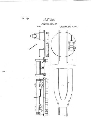
It is known that I Alexander Mc. Grew of Cincinnati, in the County of Hamilton State of Ohio, have made an improvement in Rail ways, and in the carriages for the same called the safety rail way car; which is described as follows. The Rail way is constructed by placing posts firmly in the ground of a proper degree of strength at any convenient distance, and so as to produce a plane to receive the rails to be next described. When the earth is not sufficiently firm to receive and secure the posts, stones may be put at the bottom of the holes. The rails may be of wood or iron, of a suitable size and strength; having a projection or rail rabbeted out or fastened on near the top against which the friction rollers of the guard arm of the carriage (to be hereafter described) turn; these rails are fastened firmly on the tops of the posts.
The carriage is adapted to the width of the rail way: and consists of a frame in which four or more plain wheels, with their axles, are made to turn in boxes. At each end of the carriage is constructed another frame, having two arms with bends or angles, turning on an axle fixed in the first mentioned frame. At the extremity of each of these arms are fixed two friction wheels or rollers, one turning horizontally against the sides of the rails, and the other vertically against the guard projection, or bar on the rails before mentioned, to prevent the carriage from flying off the rails —
Between the wheels of the carriage, and in the centre, are placed two spring stops, turning on an axle and having a bar or lever for turning them and causing them to rub or spring against the wheel, for regulating their speed or stopping them altogether; by which means all the wheels are profed against by moving the same lever —
To enable carriages to pass each other on the rails, an intermediate platform about double the width of the rail way is supported by posts in the manner before
Page 3.
described. At the commencement of it is an inclined plane against which the vertical friction wheels, placed at each end of the carriage, turn, and ascend the platform. On the top of the platform is a guide rail, upon and against which a grooved wheel and friction rollers turn and which serve to guide the carriage on the platform whilst turning out. This platform may be of any convenient length and immerse into a double track —
To suffer carts and carriages to cross the rail way; and also for loading the carriage, a turning platform is erected, by first driving a number of posts in the ground, forming a circle, and having a post in the middle forming a centre, on which the revolving platform is to rest and turn —
The revolving platform is made sufficiently strong and thick to bear the weight of a loaded wagon. To be in the same plane with the bed of the carriage. On the underside of the revolving platform are placed friction rollers, revolving on a board fixed on the heads of the posts, forming the circle round the centre post on which the revolving platform turns. A person hung on hinges will be attached to this revolving platform, or the rail way carriage, to cover the opening if any left between it and the revolving platform — —
The Rail way carriage will have a bed erected upon it of sufficient size and strength to receive wagons loaded with hay, or any other article without derangement of the load — Operation — —
The carriage having been placed on the rail way, and the load placed on the platform, the propelling power is applied, and the carriage moved forward; the main plain wheels turning on the top of the rails. —
The small horizontal friction wheels below, turning against the sides of the rails; and the smaller vertical friction wheels turning against the guard projection, or bars on the rails when necessary; thus the carriage would be kept on the rails, and moved forward in a straight line with much ease, velocity, and security. —
When it is required to let wagons, or any other carriages, cross the rail way, then they drive up an inclined plane upon the revolving platform, and are thus turned round until they come to the other inclined plane, connected with the other side of the road, and there descend and pursue their journey along the common road —
Also when it is required to load the rail way carriage it is
Page 4.
only needing to drive the load up the inclined plane upon the revolving platform. The platform is then turned and the carriage, together with the load is transferred to the rail-road carriage.
What I claim as my invention is the construction of the rail way with a guard or projecting piece—the vertical friction wheel: the guard arms of the carriage—the turning out platform and the revolving platform for coding roads & loading the rail-way carriage.
In witness that the foregoing is a full and true description of my invention, I hereunto subscribe my name in presence of two witnesses —
Witnesses,
William P. Elliot
L. Warner Ruggles
Alex. M. Green
Test
1856
Published accounts: journal notice
Notice in the monthly list of patents, with remarks
Journal of the Franklin Institute, new ser., vol. 8 (1831), p. 338 · View the page
38. For an improvement in Rail-ways, and in Carriages for the same; Alexander M'Grew, Cincinnati, Hamilton county, Ohio, June 13.
Remarks. We see but little that is new, and much that is old, in this specification. The rails, we are told, are to be placed upon posts, so as to produce a plane, and the whole subject is treated as though the rails were every where to be considerably elevated above the ground. The carriage is to be kept upon the rails by the use of friction wheels, instead of by flanches, and are to work against a guard or projecting piece; they are fixed upon what are called guard arms. A strap, or brake, is placed between the wheels at each side of the carriage, and these straps are to be made to bear on each of the wheels at the same time, by means of a lever. To enable loaded wagons and carts to cross the rail-road, they are to ascend an inclined plane on to a revolving platform, which turns on a pivot in its centre, and on friction rollers much like those used both here and in England. When the rail-way cars are to be loaded, it may be done from these inclined planes. There are to be double tracks in proper places, for cars to pass each other. The claim is to "the construction of the rail-way with a guard or projecting piece; the vertical friction wheels; the guard arms of the carriage; the turning out platforms; and the revolving platform for crossing roads, and loading the rail-way carriage."
About this record
- Patentee
- the Journal of the Franklin Institute, Journal
- Date
- the Name and Date index of patents, USPTO records
- Invention
- the Name and Date index of patents
- Listed in
- the Name and Date index of patents, USPTO records, Jim Shaw's X-patent list, the Journal of the Franklin Institute
- The sources give different dates; the date shown is the one most of them agree on.
- The patentee's full name comes from the Franklin Institute's journal.
- The residence comes from the Franklin Institute's journal.
- The Franklin Institute's journal gives a different date.