

Drawings and documents
National Archives restored drawings: drawing
E.M. Converse's Patent Drawing for a Beading Machine


National Archives, Restored Patent Drawings (Record Group 241) · Full-size scan at the National Archives · Catalog record
Show the text on the drawing Hide (718 words)
Words on the drawing as machine-read by the National Archives; not checked. Useful mainly for searching.
Sheet 1. E.M. Convirse / End View Beaching Mach / Roller Tools / Prymally 4 Sheeli / CLASSIFICATION / cro- / Patd July 20 1831 / Sectional / new 7 / 6618-4 / Sideriew Beading Machine / DIVISION. / Beading machine. / dheet 7. / E' / is / FL / A. Upright Pillar / B. Projecting arms / C. Studs / D. Stand with studs / E. Morable Box / F. Cylinders / G. Crank screw / H. Spring / I. Cog Gearing / K Gauge / I. Rollers / Side view Double Seaming / 1. / F4 / lmem Fearth / (cllactet Ironal)
Sheet 2. (Modet Voumid, / #6- / ID / MI / CONY / Bending / Shoets Europy / FL / gauge / A Platform / mm / B Straight bar / C. Flat bar / D. Stirrup / DIVISION. / t-8199 / NOILVOLSISSVIO / Ei. Plate Stock / E. stool Plate / (rming more) / No. 1 / G. sheel of Metal / H. Lever / ANd / I. Flat bar Lever. / K. Uprights 07 Starts. / Mach for Turning straight edges / Bendmy nachme / O 0 / Pat'd, July 20. 1831- / Brass or Copper. or Shich Iron. / manufactine of wares from Immed Plate / E. E.M. M. Converse. C onverse. / HZ / new. / that 1. 1, / your by by mustred
Sheet 3. 13. SHEET METAL WARE, MAKING, Lock E.M. learning / Originally 4 their / new / Tubing. / Convirse Rhut 2. / Straight Making, / Lock-seaming. / no. / Patd July 201831. / Grooring / Machine / my / lide view / more Furned. / ACA
Sheet 4. 113. SHEET METAL WARE, MAKING, / Tubing, / Look / Orgmally 4 Cheer / Lock-seaming. / E.ll. Learning Courrese / new / Straight, Making, / that 3. / no- / Paid July 20 1831. / Grorrung muchine / End view / A. Pillar / B. arms / C.Bed peice / D. Rib 07 skein / E. Ratchet. bar / F. Grooved Roller / G. Cog wheel mashing into Rate
Sheet 5. than to substitute another bed with groo / or outer side of the work, nothing more is n / Git be desind to lay the groove on the / upper surface and a plain rollen mind / groone / Doesn't say what metal is worked w / cylindus or shuts / Runs in the metal severses The 2 / and runs it off. / 70-6472 GSA DC / GENERAL SERVICES ADMINISTRATION / SUBGROUP / 241 / RECORD GROUP / DESCRIPTION / OTHER TREATMENT/COMMENTS / Laminated / Flattened / GENERAL SERVICES ADMINISTRATION / Encapsulated / Tears Mended / Deacidified / Removed Tape / Inks Tested / Surface Cleaned / TREATMENT / NNTS 81-11 / SERVICE ORDER NUMBER / SERIES / patents / Utility / RECORDS OF THE PATENT OFFICE / CARTOGRAPHIC RECORDS / mmc / TECHNIQUE/MATERIALS / 01 / PROCESS NUMBER / PRESERVATION HISTORY / FILED AS / RW / 8978 69 AON csa / FORM / .18199 / GSA FORM 7276 (4-79) / RW 10/31/86 / WORKER / 08/08/01 / DATE
Sheet 6. Orgmally 4 This / new 7 / USA SHEET METAL WARE, MAKING, / Ratter Lorks / E.M. Couverse. / that / IF / Roller Tools / No / CLASSIFICATION / Paid July 20 1831 / 6618- 1907 1907 / DIVISION. / Turning Edges to receive The wire / he / A. Stand / B Arbors of Rollers / C. Boxes for arbors / D. Guage / Stormy steel / E. Cog wheels / FL / F. Crank SCTCW / owner mill / G. Spiral suring / Har crites / aim B / In / 11 / A. / arbas By B / me neght in 2 the the / lept Ed hold the / Cap where I / where hirbs are / and threader / The Gurring mihi / Sland is like this / (more busind)
Sheet 7. 113 SHEET-METAL WARE, MAKING / Originally 4 Rhuh / Rollor Lorls / Roller Tools / nur 7 n / What 5. / Di / E.M. Converse. / No- / Paten ted July 20 1831 / NOISI AICI / 6618-+ / WiringMachine / A stand / B. Cylmders 07 Rollers / C Gauge / D. Forming Gauge / Patent Uffice June 30 / (Marce burned) / Made under the ctriction of the commity / Me conformity with ach of 3'. March 1837 / MLSUMO / Commissionery
Sheet 8. requally / new 7 " / 113. SHEET-METAL WARE, MAKING, / Roller Tools. / E.M. Converse / Sheet. 6. / No.- / Paid July 20. 1831, / Setting down Bottoms. Much / all Used is sand of als purpose / in operation / A. Stand / B. Fronts middle plate / classification / C. Crank & SCTCN / 6618-4 / D. Spiral Spring / LIVISION / e Tennon / joh been / (y) / bank know / foot know / I' / loh, back and foot / piece cent der neverty / V and I cant / rad / the anily and / decemed is lap place / Clear boath plate / by Sereive / 60 / (over)
Sheet 9. The common may of securing the top or cup, plate / to the "stands' (sic) is to east into the "stand" (sie) / screcopins which pass through the top plate and / receive muts to hold it in place. I secure the / top plate in stand maclines by screws passing / through the top plated and enter ing the stands / GSA DC 70.6472 / SUBGROUP / 241 / RECORD GROUP / DESCRIPTION / GENERAL SERVICES ADMINISTRATION / OTHER TREATMENT/COMMENTS / Encapsulated / Laminated / Flattened / Tears Mended / Deacidified / Removed Tape / Inks Tested / GENERAL SERVICES ADMINISTRATION / Surface Cleaned / TREATMENT / SERIES / NNTS 81-11 / SERVICE ORDER NUMBER / patents / Utility / RECORDS OF THE PATENT OFFICE / CARTOGRAPHIC RECORDS / mmc C / TECHNIQUE/MATERIALS / 11 / PROCESS NUMBER / PRESERVATION HISTORY / FILED AS / RW / my / GSA NOV 69 6768 / FORM / X8199 / GSA FORM 7276 (4-79) / WORKER / 08/18/01 / 18/28/91 / DATE
USPTO scan
The patent as scanned by the USPTO
-
 Page 1
-
 Page 2
-
 Page 3
-
 Page 4
-
 Page 5
-
 Page 6
-
 Page 7
-
 Page 8
-
 Page 9
-
 Page 10
-
 Page 11
-
 Page 12
-
 Page 13
-
 Page 14
-
 Page 15
-
 Page 16
-
 Page 17
-
 Page 18


U.S. Patent and Trademark Office · Google Patents
Show the transcription Hide (5,352 words)
Machine transcription (LightOnOCR) of the pages as scanned by the USPTO, most of them the handwritten copies made when the records were restored after the 1836 fire. Not checked; it can misread handwriting, so compare it with the scan.
Page 1.
6618X
E. M. CONVERSE.
MANUFACTURE OF WARES FROM TINNED PLATE, BRASS, COPPER, OR SHEET IRON.
Patented July 20, 1831.
4 Sheets—Sheet 1.
Page 2.
6618X
E. M. CONVERSE.
MANUFACTURE OF WARES FROM TINNED PLATE, BRASS, COPPER, OR SHEET IRON.
Patented July 20, 1831.
4 Sheets—Sheet 2.

Page 3.
6618X
E. M. CONVERSE.
MANUFACTURE OF WARES FROM TINNED PLATE, BRASS, COPPER, OR SHEET IRON.
Patented July 20, 1831.
4 Sheets—Sheet 3.

Page 4.
6618X
E. M. CONVERSE.
MANUFACTURE OF WARES FROM TINNED PLATE, BRASS, COPPER, OR SHEET IRON.
Patented July 20, 1831.
4 Sheets—Sheet 4.

Page 5.
July 20 1831
Edward M. Converse
Letters Patent dated July 20, 1831
The schedule referred to in these Letters Patent and making part of the same containing a description in the words of the said Edward M. Converse himself of his improvement in the mode of constructing machinery for the manufacture of wares from tinned plates, sheet iron, brass or copper.
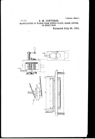
To all to whom these presents shall come. Know ye that I Edward M. Converse of Southington in Hartford County, and State of Connecticut have invented constructed made and applied to use a new and useful improvement in the mode of constructing machinery for the manufacture of wares from tinned plates, sheet iron, brass or copper described & specified in the words following (viz). My improvements in the folding machine or the machine for turning straight edges consist in the following mention particulars (viz) in a cheaper and more simple construction of the machine and in performing the work more perfectly and expeditiously. My improved machine for turning straight edges is constructed as follows. The box or platform is of cast iron about two feet long, six inches wide and one inch thick. On the under side of this are two projections for the purpose of receiving the foots of the lever or L. hereafter to be described. One of these projections is cast solid with the platform. The other is attached to the platform by screws. These projections are sufficiently deep to admit the proper motion of the lever or L. To the upper surface of the platform is screwed by screws a straight bar of cast iron eight inches long four inches wide, and about half an inch thick. This bar is so placed as to bring the foot or operating upper angle thereof over the middle of the platform. This angle is filed true & to a perfect right angle.
Page 6.
over this angle the first part of the turn or lock is given to the edge of the substance to be operated upon. This bar may be faced with a plate of hammered iron or steel and this is the preferable mode because thereby a better and more durable angle is obtained. From the upper surface and at each end of this bar and said plate with it unite two uprights or studs for the purpose of receiving and regulating the stock for the steel plate hereafter mentioned and described. These upright studs are of sufficient height and strength to keep the motion of the plate stock steady and regular. The plate stock is of cast iron being a straight flat bar about eighteen inches long, three and a half inches wide and about three quarters of an inch thick; the ends are cast with a recess for the purpose of being received by the uprights or studs and kept to a steady up and down motion. The under edge of the plate stock is also cast with a straight recess of sufficient width to receive & hold firmly by means of screws the plate of steel which is to be attached to it for the purpose of giving the turn or lock to the subject to be operated upon. This plate of steel is of equal length with the plate stock except the recesses at its ends and is about two inches wide. It is well fitted to the straight recess in the plate stock & firmly secured thereto by screws. The lower edge of the steel plate projects below the stock about half an inch. This edge is filed straight and true.
The necessary motion is given to the plate stock by means of the lever or T operating on its pivots in the projections under the platform. The part of the T or lever corresponding with the upper marks of the letter T has a pivot on each of its ends having holes in the projections on the under side of the platform. The plate stock is connected to this part of the lever or T by means of two iron straps or strips, the upper ends of which are attached
Page 7.
attached by screws to the backwise of the plate stock. These straps or straps pass down through holes in the flat bar and platform, and their lower ends are attached to the lever or T by means of a hinge operating as a hook and thimble. The part of the lever or T to which the straps are attached must lie somewhat back of the axis of the pivots, so as to give the necessary motion to the plate stock, when the handle or lever part of the T is raised or depressed. By this means when the lever of the T is raised the plate stock and its steel plate are carried up by means of the strap or straps. When the lever of the T is depressed the plate stock and plate are brought down in such manner as to give the first turn to the edge of the substance to be operated upon. The second and final turn of the lock is effected by means of a flat bar of cast iron of equal length with the plate stock. This bar is about two inches wide and one inch thick, having pivots at each end, the pivots project from the lower corner of the bar in such manner as to have their centres in a line with the lower angle of the bar. These pivots enter iron boxes which are attached to the ends of the straight bar by means of screws. The boxes project in front of the straight bar far enough to receive the pivots. That angle of the flat bar from which the pivots project is also filed true and square.
One end of the flat bar is attached to lever or handle so turned as to extend back in the same direction as the handle of the T. By this handle or lever motion is given to the flat bar. This handle being raised the flat bar lies upon the platform. The lever of the T being also raised the plate stock and steel plate are carried so as to present the edge of the material to be operated upon into the machine (the width of the lock being regulated by the gauge hereafter described). The lever of the T is
Page 8.
then brought down this motion brings the steel plate across past the operating angle for the straight bar. This gives the first turn to the fold or lock. The handle or lever of the flat bar is then brought down, this motion turns up the flat bar bringing up with it the substance to be operated upon, then by giving the second and final turn of the fold or lock, the handle of the flat bar is then raised. The lever of the V is then raised & the thing operated upon is released from the machine.
The width of the fold or lock is regulated by a movable gauge made of a plate of hammered iron. This gauge lies flat upon the upper surface of the straight bar and is kept in place by means of a screw passing through a mortise in the centre of the gauge, the mortise is made larger than the screw pin so as to admit of sufficient motion to the gauge. The head of the screw rests on a button of brass or iron which covers the mortise. This button is not attached to the gauge. The gauge is advanced or brought back by means of two screws one operating at each end of the gauge. These screws lie horizontally passing through female screws or nuts which are placed or made in projections rising from the upper side of the straight bar and entering female screws or nuts which are made in projections at each end of the gauge. The parts of the screw pins next to the heads of the screws are cut to the right, the other part next to the point of the screw pins is cut to the left, so that by turning the screws to the right, the gauge is carried forward and so vice versa. When the gauge is carried forward the width of the fold or lock is diminished and when brought back the width is increased.
This machine is affixed to its bench by means of bolts passing through the platform & the bench. The platform must be sufficiently above the bench to give the necessary room for the motion of the lever of the V.
Page 9.
points in the machine consist further in the method of discharging the work from the machine, the cheapness and permanency of its construction in the simplicity in the manner of finish of the work, also the increased rapidity of the operation.
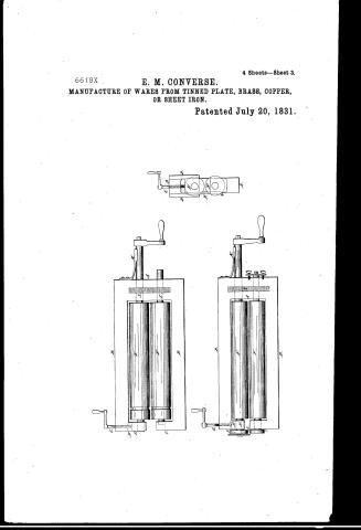
My improved gearing machine is constructed as follows. Fig. 1. The frame is of cast iron (and is cast solid) consisting of an upright pillar about eight inches in length with a horizontal arm at each end of the pillar, extending from it at right angles forming together three sides of an oblong square. These arms are two feet in length and about two inches thick; the pillar and upper arm are square except the corners of the upper arm are a little chamfered off. The upper surface of the under arm is flat and true except a rib or sheen in the centre of that surface extending the whole length of it. This rib or sheen is a half oval and uses about half an inch & is cast solid with the frame. The object of this rib or sheen is to fit & fill the groove made in a movable bed piece of cast iron hereafter described. The bed piece is about two feet long being straight and flat upon its under surface except a groove extending its whole length fitted to receive the rib on the lower arm. The upper side of the bed piece except at the end which is to be placed next to the upright pillar of the frame is shaped to a flattened half round, leaving however on the top a plane of about half an inch wide. Upon this bed the seam to be grooved is placed. At the end of the bed piece next to the pillar of the frame is a knob or projection rising on the right-hand side for the purpose of sustaining the end of the ratchet bar. The ratchet bar is a straight arm of equal length with the bed having teeth or cogs on its upper surface or side. The end of the ratchet bar which rests upon the knob of the bed, has also a knob or projection extending a little down from the lower surface or side. At these knobs the ratchet bar and the bed are confined together with
Page 10.
with a screw in such manner that the ratchet bar extends along over the right side of the bed. To the end of the upper arm of the frame is attached by screws a small frame or stand containing boxes to regulate the motion and pressure of the grooved roller hereafter described. This frame or stand is fixed to the under side of the upper arm of the stand, a grooved roller about three inches in diameter & about three quarters of an inch thick is placed in this stand. This roller is so placed as to lie directly over the upper surface of the bed.
To the right side of the roller and on its arbor is attached a small cog wheel with teeth or cogs fitted to mesh with the cogs on the ratchet bar. Through this cog wheel and the roller passes an arbor turned by a hand crank. The arbor is placed in movable boxes contained in the stand. These boxes are governed by screws in the top of the stand regulating the pressure of the grooved roller upon the bed. When the work is to be grooved turn the crank so as to bring out the ratchet bar and the bed which move together, lay the edge of the work on the bed immediately under the grooved roller, then turn the crank forward. This moves back the bed the work lying upon it; the grooved roller passes over the work, the crank is then turned backward which motion carries forward the ratchet, the bed and the work passing again under the grooved roller, is discharged from the machine & the operation is completed. This machine is confined to the block by means of a tenon or projection from the bottom of the stand under the pillars & lower arm. This tenon is cast solid with the frame having a hole or holes to bolt through to the wood. The right side bar through which the arbor passes comes across so as to embrace the ratchet bar keeping it in its place. No tools work is required for this machine except the small cog wheel, it performs its work in a better manner than any other machine used for
Page 11.
the same purpose. If it be desirable to lay the grooves in the upper or outer side of the work, nothing more is necessary than to substitute another bed with a groove on its upper surface and a plain roller without a groove. I claim as my invention the movable bed of this machine and the plan of keeping that part of the work to be operated upon under the direct pressure of the roller without any spring or bending in the the catch bar. My improved machine for heading stove pipes and articles of tinned or copper ware is constructed in manner following. A stand or frame of cast iron the whole cast solid having an upright pillar six inches in length three inches wide, about two inches in thickness with two horizontal projecting arms eighteen inches long and of sufficient size and thickness to withstand the necessary pressure of the operation. At the end of the lower arm rides a stud for the purpose of receiving on a socket the axis of the lower cylinder; this stud is cast solid with the frame & rises from the upper surface of the lower arm sufficiently high to free the roller or cylinder from contact with the lower arm. To the end of the upper arm is fixed by means of screws a cast iron stand with two projecting studs chamfered on their insides to receive and hold a movable box, against this box the axis of the upper cylinder or roller rests & is regulated by it in the manner. A space is left open on that side of the stand permitting the insertion of the articles to be headed between the cylinders and within the frame or stand. Through the upper part of this stand for the boxes is inserted a crank wheel which operates upon the box so as to depress at pleasure that end of the upper cylinder. That end of the upper cylinder is kept in place by means of a spring at the other end, as hereafter described. The axes of the cylinders or rollers at their opposite ends (that is) the ones next to the upright part of the stand or frame, pass through holes in the upright pillar.
Page 12.
The
7/20/1831 6618×
pillars of the frame having on their unders & within the pillars, half or iron egg wheels so fitted as to match accurately together. The arms of the upper cylinder extends out five or six inches to receive a crank by which motion is given to the cylinders. A smart spring is fitted on to the outside of the upright pillar extending out with a proper curve or angle so as to bear upon the long arm near the part on which the crank is fixed with sufficient force to keep to its place (under the box) the other end of the upper cylinder.
The inner surfaces of the horizontal arms of this machine should be somewhat hollowed so as to admit the more room for the rollers or cylinders within the frame. The pattern of the head is turned near the end of the cylinders farthest from the upright pillar of the frame. Upon the right hand of the horizontal arms of the frame we see projecting a little, the one upwards & the other downwards & extending from near the pillar to the head pattern on the rollers. Between these projections is placed a perpendicular iron gauge with a groove in each end fitted to the projections on the arms. This gauge is moveable backward and forward, to regulate the distance to which the article to be headed is admitted into the machine & to keep the article steady in place. This gauge is secured & regulated in place by means of a screw passing through the top of the lower groove of the gauge & resting its end against the projection on the lower arm of the frame. I claim by way of improvement on this machine the manner of constructing the frame or stand, the principle of admitting the work to be geared within the frame of the machine, the manner of constructing the gauge and the facility and exactness of the operation. My machine for double seaming the bottoms of round or oval vessels is constructed on the frame or stand of the leading machine & one nearly similar to it, all the parts are similar in both except the construction of the cylinders & rollers and the gauge which is not wanted in the double seaming machine.
Page 13.
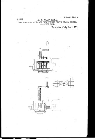
fact is retained and another set or pair of cylinders interposed to get on with the addition of a regulator for the power cylinder to be hereafter described. The under cylinder of this machine is of iron with a roller of case hardened iron on the end farthest from the pillar or upright part of the frame. This roller is about two inches in diameter and half an inch thick, turned to a true face and plain surface upon the outer circumference. This roller lies without the body of the frame. The upper cylinder is furnished on the same end with a roller of case hardened iron or steel two and a half inches in diameter. The outer rim of this upper roller is grooved all around in a slanting direction for the purpose of drawing the vessel to be double seamed close to the work, and so to prevent a vacancy near the end of the operation. The upper roller operates exactly above the under roller and is forced and held down by the crank screw before described. To the face of the upper roller is attached by a screw made upon the projection of the arbor, a plate of hardened steel which projects about a quarter of an inch beyond the upper roller. The office of this projection is to force down to a double seam the projecting ridge of the bottoms put together in the common method and this force is applied by the arm or projection formed by the face. Motion is given to the cylinders by the same described hand crank or similar pair of any wheels as applied to the cylinders to give the corresponding motion of the cylinders, but the upper roller being considerably larger than the under one produces an accelerated motion in the upper roller, this is necessary to the operation for if both rollers were to move together with equal velocity the work at near the end of the operation would be left imperfect. For the purpose of keeping the lower cylinder in place there is attached to the outside of the pillar of the frame a regulator constructed and applied as follows. The arbor of the cylinder projecting through the pillar about three quarters of an inch, a channel or groove is cut across this projection of the arbor, a small plate of steel
Page 14.
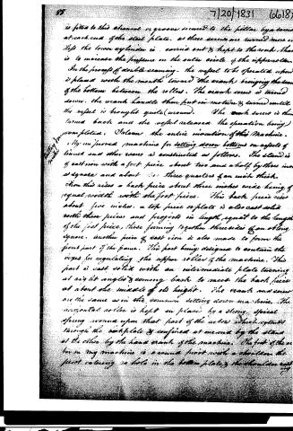
is fitted to this channel or groove secured to the pillar by a screw at each end of the steel plate. As these screws are turned more or less the lower cylinder is carried out & kept to the work. That is to increase the pressure on the outer circle of the upper roller.
In the process of double seaming, the vessel to be operated upon is placed with the mouth toward the crank, bringing the seam of the bottom between the rollers. The crank screw is turned down, the crank handle then put in motion & turned until the vessel is brought quite (around). The crank screw is then turned back and the vessel released. The operation being completed, I claim the entire invention of this Machine.
My improved machine for setting down bottoms on vessels of tinned and other uses is constructed as follows. The stand is of cast iron with a foot piece about two and a half by three inches square and about three quarters of an inch thick. From this rises a back piece about three inches wide being of equal width with the foot piece. This back piece rises about five inches. A top piece or plate is also cast solid with these pieces and projects in length equal to the length of the foot piece, these forming together three sides of an oblong square. Another piece of cast iron is also made to form the front part of the frame. This part being designed to contain the boxes for regulating the upper roller of the machine. This part is cast solid with an intermediate plate turning at right angles & coming back to meet the back piece at about the middle of its height. The cranks and screw are the same as in the common setting down machine. The horizontal roller is kept in place by a strong spiral spring wound upon that part of the axis which extends through the back plate & confined at one end by the stand at the other by the hand crank of the machine. The foot of the axis in my machine is a conical foot with a shoulder, the pivot entering a hole in the bottom plate, the shoulder resting
Page 15.
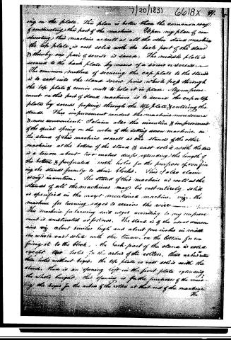
ing on the plate. This plan is better than the common way of constructing this part of the machine. Upon my plan of constructing this machine as well as all the other stand machines the top plate is cast solid with the back part of the stand & thereby one pair of screws is saved. The middle plate is secured to the back plate by means of a screw or screws. The common method of securing the cap plate to the stand is to cast into the stand screw pins which pass through the top plate & receive nuts to hold it in place. My improvement on this part of stand machines is to secure the cap or top plate by screws passing through the top plate & entering the stand. This improvement renders the machine more secure & more convenient. I claim also the invention & improvement of the spiral spring on the axis of the setting screw machine in the stand of this machine as well as the stands of the other machines at the bottom of the stand & cast solid with the stand is a tenon about two inches deep extending the length of the bottom & perforated with holes for the purpose of confining the stands firmly to their blocks. This I also claim as my invention. The stand of this machine as well as the stands of all the machines may be cast entirely solid as specified in the next mentioned machine, viz. the machine for turning edges to receive the wire.
The machine for turning said edges according to my improvement is constructed as follows. The stand is of the usual dimensions viz. about six inches high and about four inches in width. The whole cast solid with the tenon on the bottom for confining it to the block. The back part of the stand is cast except two holes for the axles of the rollers, these axles enter the holes without keys. The top plate is cast solid with the stand. There is an opening left in the front plate extending the whole height. This opening is for the purpose of the receiving the keys for the axles of the rollers at that end of the machine.
Page 16.
7/20/1831 6618X
The boxes are kept in place by means of an iron rod on each side of the boxes. These rods pass down through the top plate & into the bottom plate of the machine, having a screw cut at their lower ends, these rods fill the grooves cut in the ends of the boxes & keep them in place. The boxes may be made of brass, composition metal or cast iron. The gauge for this machine has a shaft or rod passing through the front & back plates of the stand & having a spiral spring wound on the whole length between the parts of the stand. The rod comes through the back plate of the stand about half an inch having a screw cut upon that end about an inch and a half in length so as to receive on the inside of the back plate a nut with short arms like a windlass. The spiral spring presses against this nut to keep it in place. By turning this nut is carried forward & brought back at times under the operation of the spring. The rollers are supplied with cog wheels & the boxes governed by a crank, screw in the usual manner. I claim the invention of the manner of regulating the gauge of this machine & the manner of constructing the stand. Between the boxes of this machine I place a small spiral spring for the purpose of eliciting the upper roller to receive the work previous to turning down the crank screw. The ends of this screw are let into small holes in the boxes. This spring is applied by me to all the machines having boxes except the setting down machine where it is not required. This spring I claim as my invention. The cog wheels are put into the arbor where the stand is cast entire by screws cut on the arbor. The one to the right & the other to the left: female screws being cut to meet them & match with them in the arbor. The stand of my turning machine is constructed in the same manner as the one above described. The gauge is regulated in the same manner, as the edge of the upper edge of the upper roller of this machine is apt to fail, I construct that by a force in view of spring tempered steel & secured
Page 17.
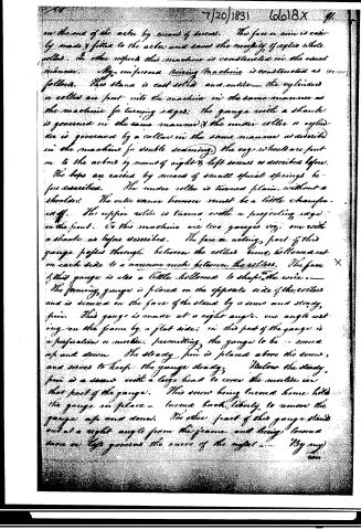
on the one of the other by means of screws. The face or arm is easily made & fitted to the other and saves the necessity of extra wheels. In other respects this machine is constructed in the usual manner. My improved twining machine is constructed as follows. The stand is cast solid and entire—the cylinders or rollers are put into the machine in the same manner as the machine for turning edges; the gauge with a shank is governed in the same manner & the under roller or cylinder is governed by a collar in the same manner as described in the machine for double seaming, the cog wheels are put on to the arbor by means of right & left screws as described before. The boxes are carried by means of small spiral springs before described. The under roller is turned plain without a shoulder. The outer canes however must be a little chamfered off. The upper roller is turned with a projecting edge on the front. To this machine are two gauges viz. one with a shank as before described. The face or acting part of this gauge projects through between the rollers being hollowed out on each side to a narrow notch between the rollers. The face of this gauge is also a little hollowed to shape the wire. The forming gauge is placed on the opposite side of the rollers and is secured on the face of the stand by a screw and steady pin. This gauge is made at a right angle, one angle resting on the frame by a flat side; in this part of the gauge is a perforation or mortise, permitting the gauge to be moved up and down. The steady pin is placed above the screw, and serves to keep the gauge steady. Below the steady pin is a screw with a large head to cover the mortise in that part of the gauge. This screw being turned home holds the gauge in place—turns back, liberty to remove the gauge up and down. The other part of this gauge stands out at a right angle from the frame and being lowered more or less governs the curve of the rope. By my
Page 18.
7/20/1831 6618X
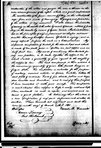
construction of the rollers and gauges the wire is thrown on the outer circumference of the wheel, which is a great improvement. The construction of the frame, manner of fitting on the wheels with cogs, form, and mode of managing the gauges, and formation of the rollers, is my invention. I also claim the invention of drawing on the wheels to the wires by means of screws, instead of putting on the wheels by means of square tenons. Machine constructed on the principles of my improvement are cheaper and more durable than any heretofore known, less liable to injury, and in many respects perform the work in a better manner. My improved composition of metals for the stands, boxes and wheels is made of two parts zinc, or spelter, one part copper and one half part tin. My mode of combining these metals for my composition, is to melt together the copper & tin to which I add a quantity of zinc equal to the weight of the copper & tin. The hard compound is then added to the remaining quantity of zinc, both parcels being in a fused state. This composition is valuable for the purpose of making various articles, as spoons, buckles, buttons, the erect parts of anirons; heads of fire shovels, pokers and tongs, iron handles and knuckles, and to many of these purposes I have converted it with good success. This composition is much cheaper than copper or brass, is easily cast and kept clean, contracts no rust or oxide, and receives and retains a good polish. In testimony that the above is a true specification of my said improvements as above described, I have hereunto set my hand and seal this twenty-ninth day of March A.D. 1831
Witnesses
Barnes Lowrey
Joel Holcomb
Edward A. Converse
Filed
A.D.
(8544 wtd)
Published accounts: journal notice
Notice in the monthly list of patents, with remarks
Journal of the Franklin Institute, new ser., vol. 9 (1832), p. 42 · View the page
8. For Machinery for Manufacturing Tin Ware; Edward M. Converse, Southington, Hartford county, Connecticut, July 20.
Remarks. Those acquainted with the progress made within the last thirty years in the manufacturing of tin ware, know, that with the exception of soldering the work together, nearly the whole of the labour is performed by machinery. The present patentee has described and figured machinery for turning straight edges for grooving-for double seaming-for setting down bottoms on vessels for turning edges for wiring, and for burring. In their general construction these machines resemble those heretofore known, but with certain alterations which the patentee believes to be improvements; and the whole description of which occupies more than twenty-four pages. He says that they are cheaper, more durable, and perform the work better than any others. The frame work of his machinery, the wheels, boxes, and most other parts, are made of a compound of zinc, copper, and tin, in the proportion of ten parts of the first, one of the second, and half a part of the third. He mixes these by melting together the copper and tin, to which he adds as much zinc as the weight of both. This mixture is then combined with the remainder of the zinc, in a fused state. This metal, we are told, is valuable for making a great variety of articles in domestic economy; that it is recommended by its cheapness, and freedom from corrosion, and that it receives a fine polish.
About this record
- Patentee
- DATAMP
- Date
- the Name and Date index of patents, DATAMP, USPTO records
- Invention
- DATAMP
- Listed in
- the Name and Date index of patents, DATAMP, USPTO records, Jim Shaw's X-patent list, the Journal of the Franklin Institute, Burke's List of Patents (1847)
- The Franklin Institute's journal spells the name differently.
- Burke's 1847 Patent Office list gives the same patent.