

Drawings and documents
National Archives restored drawings: drawing
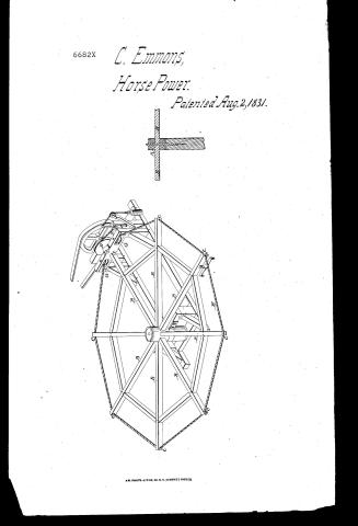
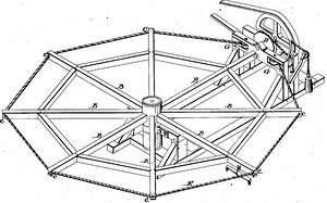
Calvin Emmons' Patent Drawing for a Machine for Horse Power

National Archives, Restored Patent Drawings (Record Group 241) · Full-size scan at the National Archives · Catalog record
Show the text on the drawing Hide (57 words)
Words on the drawing as machine-read by the National Archives; not checked. Useful mainly for searching.
MECHANIC AL / 185. D Mechanical Motors, / Horse-power,s Drums. / Emgineering June Lower / P. / CLASSIFICATION / 6682-X / DIVISION. / Aalvin Emmoks / Horse Pover. / Patented. aug 2:1831 1831. / Patint office 29 Lept1838 / Made under the direction of the Commyrown / of Patients in conformity with acts march 1837 / Commitions of Palants
USPTO scan
The patent as scanned by the USPTO
-
 Page 1
-
 Page 2
-
 Page 3
-
 Page 4
-
 Page 5


U.S. Patent and Trademark Office · Google Patents
Show the transcription Hide (919 words)
Machine transcription (LightOnOCR) of the pages as scanned by the USPTO, most of them the handwritten copies made when the records were restored after the 1836 fire. Not checked; it can misread handwriting, so compare it with the scan.
Page 1.
6682X
C. Emmons,
Horse Power.
Patented Aug. 2, 1831.

A.M. PHOTO-LITHO. CO. N.Y. (OSBORNE'S PROCESS)
Page 2.
To all to whom these presents shall come: We it known that I Calvin Emmons of the City County of New York, have invented a new and useful improvement in the mode of applying Horse power for propelling machinery and that the following is a full and exact description of the Construction and operation of said improvement in the Horse power as invented by me. A centre part or hub from two to two feet in diameter made of plank or of one solid piece of wood cut from off a log, & should be iron bandled for it may be made of Cast iron; its axis perpendicular & kept in its position by a centre axle or pin on which it turns, which communicates with a solid fixture below the hub. Notches are made in this centre part or hub to receive the ends of the arms 73 74 75 76 77 78 79 80 which are usually from six to eight in number from 10 to 15 feet in length; one end edge of the ends of which enters the hub & on a band tail that it may be fastened with a key which may be drawn in and taken out at pleasure, or they may be fastened any other convenient way. A notch is cut horizontally in the outer end of each of the arms usually of an angle of about 45 degrees & ascribe to the ends of the arms with a point.
Page 3.
wooden studs or braces between each of the arms to keep them at equal distances apart (a chain or rope may be substituted in this stead) braces should be placed from the lower part of the huts to the under side of the arms when the arms are so long & heavy as to require being supported. D a wheel & cylinder placed just within the circle which the outer ends of the arms describe made from one solid log and placed with its axis horizontal and supported in its position by journals resting in a proper fixture or frame. This wheel & cylinder may be made separately of plank or boards & placed on the same shaft at such distance apart & made such size as may best suit the purpose intended. E. a Rope the ends of which are fastened to each other by an iron hook & eye that it may be shortened or lengthened, as occasion may require by unhooking & twisting or untwisting. This rope is placed around in the circles of the outer ends of the arms & passes once around the wheel D (instead of this rope a chain may be substituted) F. a movable wheel or pully so placed that it may press outwardly against the rope by means of a weight with which it communicates by a rope passing over a pulley or the rope may be made fast to a large pulley or cylinder & a weighted lever attached to a spring may be substituted in order to keep the rope equally tight should it stretch or shrink. G. a friction or gauge wheel placed in a proper position to guide & cause the rope to turn.
Page 4.
into the wheel D smoothly. When the above described apparatus or horse power is to be put in motion one or more horses are placed between I near the outer ends of the arms just inside the rope & hitched to the arms immediately behind them by means of which they are made to walk in circular track and causing the arms to revolve - the rope being drawn tight by means of the movable wheel F. I weight will be prevented from slipping in the notches in the ends of the arms & in the grooves of the wheel D. Consequently a rotary motion will be communicated to the said wheel I drawn. The number of revolutions of the wheel D will be in proportion as its diameter is with that of the circle described by the ends of the revolving arms (deduction being made for the straight parts of the rope between each of the arms) in many instances the above mentioned wheel and drawn D. may be dispensed with by passing the rope & around a wheel on the machine which is to be put in motion & arranging the movable wheel F. & weight in any convenient place. Also the wheel D. may be placed on a shaft whose axis is perpendicular as in driving a Horse Corn Mill in which case the wheel D may be placed on the mill stone spindle. What I claim as new and as my own invention or discovery is the above described horse power or machine for the use of which I seek an exclusive privilege in the construction & arrangement of the same.
Page 5.
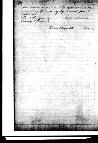
Parts above described & the application to the prospecting of machinery by animal power
Witnesses
David Chambers 3
Lincolly P. Buryer 3
Calvin Emons
Patented 2 August 1831 (864 words)
Published accounts: journal notice
Notice in the monthly list of patents, with remarks
Journal of the Franklin Institute, new ser., vol. 9 (1832), p. 111 · View the page
4. For Applying Horse Power for Propelling Machinery; Calvin Emmons, city of New York, August 2.
Remarks. A wheel twenty or thirty feet in diameter, and placed horizontally, is to be turned by a horse. The wheel, so called, consists of a strong nave, or hub, with six or eight arms, ten or fifteen feet long, projecting from it. The hub has an axis passing vertically through it, which axis is fixed firmly in a piece of timber placed beneath it. There is no rim to the wheel, but the spokes are braced together by pieces passing from one to the other, at about one-third of their length from their outer ends. This allows of a space between the project1 1 ing ends of the spokes for the horse to walk in; the wheel standing no higher from the ground than is necessary for the draft of the animal, and the traces being attached to one of the spokes. The ends of the spokes are notched, to receive a band, they being intended to operate as a band wheel; this band extends out, and passes round a whirl, from which motion is to be communicated to any machinery which is to be propelled. The claim is to the construction and arrangement of the several parts of this apparatus. Its superior advantages we do not perceive.
DATAMP: illustration
Illustrations from DATAMP

DATAMP (Directory of American Tool and Machinery Patents), via the Internet Archive · Archived DATAMP page
About this record
- Patentee
- DATAMP
- Date
- the Name and Date index of patents, DATAMP, USPTO records
- Invention
- DATAMP
- Listed in
- the Name and Date index of patents, DATAMP, USPTO records, Jim Shaw's X-patent list, the Journal of the Franklin Institute, Burke's List of Patents (1847)
- Burke's 1847 Patent Office list gives the same patent.