

Drawings and documents
USPTO scan
The patent as scanned by the USPTO
-
 Page 1
-
 Page 2
-
 Page 3
-
 Page 4
-
 Page 5
-
 Page 6
-
 Page 7
-
 Page 8
-
 Page 9
-
 Page 10
-
 Page 11
-
 Page 12
-
 Page 13
-
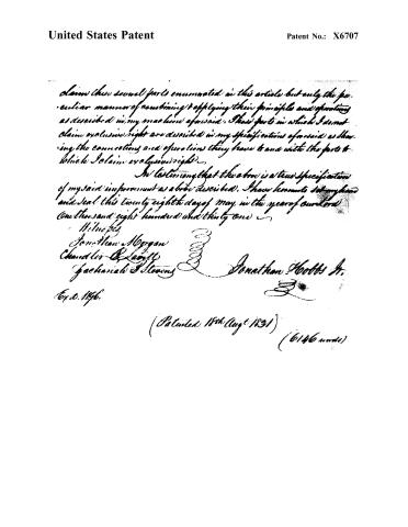 Page 14


U.S. Patent and Trademark Office · Google Patents
Show the transcription Hide (5,320 words)
Machine transcription (LightOnOCR) of the pages as scanned by the USPTO, most of them the handwritten copies made when the records were restored after the 1836 fire. Not checked; it can misread handwriting, so compare it with the scan.
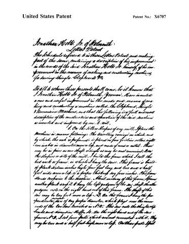
Page 2.
United States Patent
Patent No.: X6707
Jonathan Kobb, Jr. of Belmont
Letters Patent
The Schedule referred to in these Letters Patent and making part of the same, containing a description of his improvement in the words of the said Jonathan Kobb Jr. himself of his improvement in the manner of making and constructing machines for sawing shingles, clapboards &c.
To all to whom these presents shall come, be it known that I Jonathan Kobb Jr. of Belmont, (Yeroman), Have invented a new and useful improvement in the mode and manner of making and constructing a machine called, the Clapboard, Shingle & Dimension Machine, and that the following is a full and exact description of the construction and operation of the said machine as invented and improved by me. It is:
1. On the Sills or Sleepers of any mill, I place the Machine in manner following: The travelling carriage on which, and by which, the work is performed, is placed on four friction rollers, eighteen inches in diameter more or less, and made of wood or metal. These may be in pairs on one shaft, or single as may be most convenient. 2. On the Sleepers or sills of the mill, I build the frame which I call the bed work or frame, in which I hang the saws. This frame is built of plank sixteen inches high, four feet long, and two and a half feet wide more or less, of a proper thickness say four inches. The frame stands crosswise to the machine. About midway of this frame, I frame another plank across it to hang the left gudgeon of the saw shaft. The other gudgeon rests on the right hand end of this frame. The shaft of this saw may be two feet more or less. 3. On this frame I hang the perpendicular saw of any proper diameter, which plays near the inner ends of the two bars described in A. 15. This saw cuts the shingles, clapboards, and dimension stuff. 4. On the right hand end of the saw frame A. 3, I set four posts, which are not connected with it. They may be two and a half feet high, more or less. On these posts I put
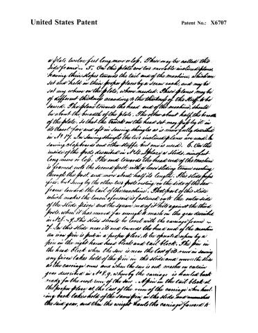
Page 3.
United States Patent
Patent No.: X6707
a plate twelve feet long more or less. These may be called the side frames. 5. On this plate are two movable inclined planes, having their slopes towards the tail end of the machine, which are set and held in their proper places by a screw each, and may be set any where on the plate, where needed. These planes may be of different thickness according to the thickness of the stuff to be sawed. The plane towards the head end of the machine, should be about the breadth of the plate. The other about half the breadth of the plate. So that the track on the head set may pass by it in its travel fore and aft in sawing shingles as is more fully described in N° 17. In sawing shingles the two inclined planes are used. In sawing clapboards and other stuff, but one is used. 6. On the inside of the posts described in N° 4, I place a slide, nine feet long more or less. The end towards the head end of the machine is framed into the second post, with a loose sliding tenon reaching through the post, and more about half its length. This slide passes free, but snug by the other two posts resting on the side of the saw frame toward the tail of the machine. That part of this slide which makes the tenon of the said is fastened onto the outer side of the slide piece and the square end of it hits against the third post, when it has moved far enough to make on the gear described in N° 8. 9. This slide should be level with the carriage frame. 7. In this slide near its end towards the head end of the machine an iron pin is put in a proper place, to be operated upon by a pin in the right hand head block and tail block. The pin in the head block when the saw is near the last of its run in sawing any piece takes hold of the pin in the slide and moves the slide as the carriage runs and when the saw is out makes on certain gear described in N° 8. 9. whereby the carriage is hauled back ready for the next run of the saw. A pin in the tail block at the proper place at the last of the run of the carriage when hauling back takes hold of the same pin in the slide, and unmakes the said gear, and then the weight hauls the carriage forward to
Page 4.
United States Patent
Patent No.: X6707
the cut of the saw, and so alternately as one shingle after another is sawed. 8. A double iron brace or vee, is fastened on to the under side of this slide near the end, towards the tail of the machine, which stands out on the inside of the machine four inches, more or less. 9. In the point or centre of this vee, the long end of an iron knee say 12 inches long, is fastened by having its end drawn to a pin and turned down through a hole in the vee. The other end of this knee is about seven inches, having the end turned down, and a notch cut in it, which notch drops on to the rim of the hollow shaft at 10. 10. A hollow shaft or cylinder is slipped onto the inner end of the shaft of a wheel described in at 12. The barrel of this cylinder is about inch and a half, and the bore about nine eighths of an inch diameter, and plays loose on the shaft of the wheel. On the end of this cylinder, next to the wheel, a rim rises five inches in diameter more or less. The short end of the knee at 9, makes on to the rim on the top and at the centre as described in at 9. On the outside of this rim and next to the hub of the wheel, is a flat iron pin and a corresponding one in the hub of the wheel. When the slide is moved by the forward motion of the carriage at the last of the run of the saw, and when run out the motion of the slide, vee, and knee aforesaid, slips the cylinder aforesaid on the shaft of the wheel towards the hub of the wheel, whereby the pin in the rim of the cylinder and the pin in the hub of the wheel are locked together and then the wheel turns with the cylinder, winds a cord around it. 11. A line, one end of which is fastened to this cylinder, the other end to the crop bar in the head end of the carriage frame, passes round a pulley which stands in front of the head friction rollers. When the gears at 8, 9, 10 are meshed on, this line winds round the cylinder, hauls round the pulley, and runs the carriage back as described in at 10, and brings the tool back ready for sawing the next shingle, see also at 7. 12. At the tail end of the machine on the right side, the wheel on
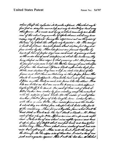
Page 5.
United States Patent
Patent No.: X6707
whose shaft the cylinder is to works, is placed. This wheel may be four feet in diameter more or less, and may be driven by a band or any other power. It is made and hung as wheels commonly are, in the rim of this wheel, any number of spoke sheaves, which may be necessary, may be placed, having the edges come out on the inside of the rim (by which the shingles may be joined). 13. The carriage is built as follows. Two side pieces about sixteen feet long, and four inches by six. These side pieces are framed together by two or six bars of proper size near each end. A groove is made in the under side of each side piece, in which the trucks run, they being shaped on their cages to that groove. 101. This frame may be four feet wide more or less. 14. On this carriage frame about four feet from the head end, I place a block eight inches high, four thick, and sixteen long more or less, on each side piece of this frame, and bolt them on stationary in their proper places. These should be exactly opposite. Towards the tail end of the carriage I place another block on each side piece like the others. These also are bolted on, but are movable to accommodate different lengths of stuff to be sawed. On each of these sets of block I bolt a timber seven inches by four, reaching across the ends flush with the outside of each block. On the inside of each of these timbers I bolt a piece of like length, seven inches by three, with three or more bolts. These inside pieces and the timbers to which they are bolted form clamps which hold other parts of the machinery. These pieces altogether form what I call the head stock or block and the tail stock or block. 15. Between each of these clamps, 1014. I place an iron stirrup made as follows. I take a bar of iron about nine eights square, and bend it up in form of a staple about one foot broad and twenty-five inches long. Then I turn about seven inches of each end side-wise to a right angle. These ends so bent, I call the toe of the stirrup. On the upper side of these two, I rivet a bar of iron inch and a quarter square. This I call the toe bar, at the head
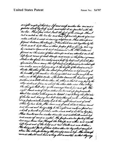
Page 6.
United States Patent
Patent No.: X6707
a right angle of the two I frame bars and another bar one and a quarter inch by half inch, and rivet it in, parallel with the two bar. These form what I call the foot of the stirrup. Then I cut a notch in the two bar and head, to place the points of an iron roller, which is used in sawing clapboards. These stirrups are placed between the clamps No 44 which are set together by the bolts so as to hold them in their proper places firmly, and may be raised or lowered to suit convenience. 16. The setters are placed on the inside of these stirrups and are attached one to the left hand corner of each stirrup, and made in the following manner. I take a bar of iron two inches and a half by half inch, from the piece aforesaid I turn down the left hand end perpendicular about eight or ten inches more or less according to the height of the head and tail blocks. The other of the bar about four feet more or less according to the breadth of the machine lies horizontal, and reaches across the machine over to the plate No 44. The setter towards the head end of the machine, is a little shorter than the other so that it may pass by the other inclined plane on which the other setter rises when setting the shingles bolt No 5, as the carriage travels for and aft. The right hand ends of these setters are turned up perpendicular about two inches with a quarter twist, so as to bring the flat side of the bar out, having two bolt holes through each. A slide standing perpendicular, is attached to the right hand end of each setter by two bolts. The lower end of each slide is drawn round and turned out horizontally to the right and makes a pivot on which a track or friction roller runs, and is held on by a pin. These tracks are ten inches diameter and in thickness more or less and made of wood or metal. The perpendicular parts of the setters come down low through the clamps and within and near the left hand end of the head and tail blocks and near to them. The horizontal parts of these setters should lay about one foot above the clamps holding the stirrups more or less. The slides of aforesaid should each have a long slot or notches so that they may
Page 7.
United States Patent
Patent No.: X6707
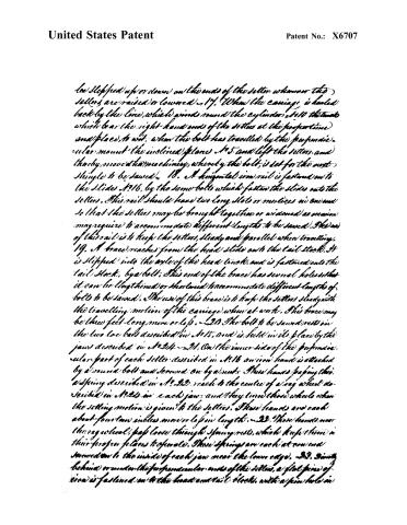
be slipped up or down on the ends of the setter whenever the setters are raised or lowered. 17. When the carriage is hauled back by the line, which winds round the cylinder, 10 the tacks which bear the right-hand ends of the setters at the perpendicular and places, to wit, when the bolt has travelled by the perpendicular, under mount the inclined planes, 5 and left the setters, and thereby move it to machinery, whereby the bolt, is set for the next shingle to be sawed. 18. A horizontal iron rail is fastened on to the slides, 16, by the same bolts which fasten the slides onto the setters. This rail should have two long slots or mortices in one end so that the setters may be brought together or widened as occasion may require to accommodate different lengths to be sawed. The use of this rail is to keep the setters, steady and parallel when travelling. 19. A brace reaches from the head slide onto the tail stock. It is slipped into the axle of the head stock, and is fastened onto the tail stock, by a bolt. This end of the brace has several holes so that it can be lengthened or shortened to accommodate different lengths of bolts to be sawed. The use of this brace is to help the setters steady with the travelling motion of the carriage when at work. This brace may be three feet long more or less. 20. The bolt to be sawed rests on the two toe bars described in 15, and is held in its place by the jaws described in 24–21. On the inner side of the perpendicular part of each setter described in 16 an iron hand is attached by a round bolt and screwed on by a nut. These hands, passing through a spring described in 22, reach to the centre of a rag wheel described in 22 in each jaw, and they turn these wheels when the setting motion is given to the setters. These hands are each about four to ten inches more or less in length. 22. These hands near the rag wheel, pass loose through springs, which keep them in their proper places to operate. These springs are each at one end screwed on to the inside of each jaw near the lower edge. 23. Behind or under the perpendicular ends of the setters, a flat piece of iron is fastened on to the head and tail stocks, with a pin hole in
Page 8.
United States Patent
Patent No.: X6707
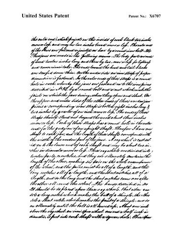
the outer end, which project on the inside of each block ten inches, more or less, and may be two inches broad more or less. The outer ends of the jaws are fastened or jointed on here by a round iron bolt. The jaws are made in the following manner: The body parts are made of wood twelve inches long and three by two, more or less for lightness and convenience sake. The ends toward the head and tail blocks are scarfed down thin. On the under side an iron strap of proper dimension is fastened. In the outer ends of these straps is a round hole in each, whereby the jaws are fastened on to the iron pieces described in § 23 by a round bolt and a nut which make the joints on which the jaws swing, when they open and shut. On the upper and under sides of the other ends of these wooden jaw pieces a corresponding iron strap is bolted eight inches long & two inches by quarter of an inch more or less. The ends of these straps should stand out beyond the wood about three inches more or less. Each of these straps has a round hole in the outer end for the guage or of an upright shaft. Therefore I have one shaft to each jaw, and the length of these shafts corresponds with the width of the wooden part of the jaws. A sag wheel is cast solid on to the lower end of each shaft and may be about two inches in diameter more or less. These sag wheels are divided into twelve parts, or notches, and they are alternately one twice the length of the other, making six pairs on the whole circumference of the wheel, and the pairs must be all of a length, and the long notches all of a length, and the short notches all of a length, and so the long and the short notches come one after the other all round the wheel. The hands described in § 20 should be so placed upon these sag wheels, that when one set a long notch which makes the butt of a shingle, the other set a short notch, which makes the point of a shingle, and so on alternately until the bolt is all sawed up. About one inch above the sag wheel, an iron spur wheel, one and a half inch in diameter, is put into each shaft with a square hole. Thus, four
Page 9.
United States Patent
Patent No.: X6707
Wheels may be fastened on, or put on loose at pleasure and their diameters may be varied at pleasure, so as to set thicker or thinner if desired. These spur-wheels bear hard against the ends of the belt, and as the hands turn the sag wheels, the spur wheels carry forward and set the belt for the next shingle to be sawed. A Screw fastens the under iron strap on each jaw, which bears hard against the underside of each sag wheel which makes the wheels turn hard enough to stand firm in their places where the hands set them. The inner ends of these jaws rest on the right hand toe bar of each Stump. In the back side of each jaw and near the spur wheel is an iron hook into which the two inclined braces are hooked as described in m.25. All these parts make the jaws. 25. Between the head & tail blocks a flat piece of iron, three feet long, one inch by quarter inch more or less, having its outer end full of holes, about half inch in diameter, passes loose through a mortice in the left side piece of the carriage. On the upper side of the inner end of this piece, is an iron pin of proper size and length. This I call the centre piece. A piece of iron of similar size, having its inner end full of holes, is hitched on to the pin on the inner end of the centre piece aforesaid and passing under the toe bar and heel bar of each Stump, turns up behind and over each heel bar, and by a hole is slipped on to the fork on the backside of each jaw. These two pieces are called the inclined pushing and hauling braces. These operate in the following manner. When the centre piece is hauled out, these braces haul the jaws together and set the spur wheels hard against each end of the belt, and hold it firm in its place. When this centre piece is hauled out caught it is held in its place by a pin passed through one of the holes and is set behind a strong spring, which holds all firm in their places. When this centre piece is pushed in, the braces open the jaws and let the belt loose. 26. The Spring which holds the centre piece 25, is fastened on to the left side of the carriage frame, and may be of steel or wood, as may be most convenient & should be of proper strength and length. 27. A piece of wood is in the length
Page 10.
United States Patent
Patent No.: X6707
the bolt may not come too hard against the saw at the first of its cut. On the side of the roller and against the ending of the diminution of the spiral groove, I have a dozen holes, more or less at different distances from the center. Into any one of these holes I put a pin which can be shifted at pleasure. This pin should be so placed that when the carriage is hauled back to the machine set for the next cut the line shall bear a little against this pin so as to start the carriage easy. Then when the pin leaves the line, the line hangs at the diminution of the spiral groove aforesaid, which gives the weight a light power upon the carriage when the saw first begins to enter the bolt which increases as the roller turns forward until it comes to its full strength on the circumference. I have found from practice that four ten pounds are about right for the weight. This may be increased or decreased according to the power required to drive the saw. I make the weight by putting small rocks or any heavy article in a box which can be increased or decreased at pleasure. I set this roller or pulley in the top of a short post which is framed into any convenient timber in the mill and so placed that the tail end of bar of the carriage shall come near to it when the saw has made its run. This machinery feeds the bolt to the saw when cutting, but water power or any other may be had if preferred.
I have now described the machine and its parts and their operations used in sawing shingles and proceed to describe those parts used in sawing clapboards. 3D. In preparing the machine for sawing clapboards, I first remove the jaws and their apparatus, then remove the jaws and all their apparatus the inclined braces and center piece, and the setter on the tail stock. Then having cut notches or grooves boxes in the toe bars and heel bars, on the inner ends, I place in an inverted roller upon the right hand side of the foot of each stirrup. The roller on the foot of the stirrup in the tail stock has a straight smooth barrel. The roller in the foot of the stirrup in the head stock has a ring wheel, on the end next to the heel bar, and the other end flat. The ring wheel is used to set by. One end of the log rests on the flat end. These flats are designed to hold on to the log and make it move regularly.
Page 11.
United States Patent
Patent No.: X6707
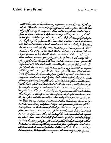
with the roller, when the setting apparatus moves the roller by the rag wheel. The other end of the log rests on the other roller, the roller moving with the log at every set. These rollers may be six inches long, 1/4 four in diameter, iron or lap, as necessary. The rag wheel may be the depth of its notches larger than the roller. 33. To the end of the perpendicular part of the setter on the head stock, I attach at hand by the same bolt and nut as before, which reaches on to the rag wheel. 34. I set the roller and sets the log, when the setting motion is given to the machine. The setter on the tail stock is not used nor the rail in sawing slab boards. 34. On the back side of the heel bar, on the head stock stirrup, a strong spring is fastened. A screw in the end of the spring passes loose through a hole in heel bar and set hard against the rag wheel. 32, which holds the roller firm in the place where it put by the hand, when the setting motion is given to it in every set of the log, when sawing. 35. On the inside of the head stock and tail stock I fasten a perpendicular piece of flat iron with rivets two feet long, and inch and a half by half inch. To the left of these perpendicular pieces and about five eighths of an inch distant, I fasten another piece on the head block and tail block of like dimensions, at the lower end by one pin or rivet so that it may be turned down and up as occasion may require. These are called the centre guides, and the centre between these two pieces should come directly over the perpendicular saw. When the log is put into the machine these swing pieces are lowered down to the left, the log is then rolled in, and then these swing pieces are lowered up, and then each pair of these centre pieces confines one of the centre pins in the two ends of the log, the lower ends of these centre pieces should come down as near as possible to the under sides of each clamp to which it is fastened. Then the centre of the rollers on which the log rests are about three inches to the left of the centre of the log, which makes the log bind hard enough upon the rollers, so that it shall not slip. These centre pins in the ends of the log are about five eighths of an inch diameter and should be screwed or driven in three or four inches from the log, so as to stand firm. Between the centre guides the wood may cut away so as
Page 12.
United States Patent
Patent No.: X6707
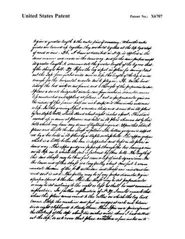
to give a greater length to the entire pins if necessary. When the entire guides are turned up together, they are held together at the top by a clef of wood or iron. 36. A brace as described in No. 19, is applied in the same manner and made in the same way, and for the same purpose except its greater length, to accommodate the greater length of the log over that of the single bolt. 37. Before the log is put in place for sawing I cut out the top four inches wide more or less, the length of the log, is wide enough for the horizontal circular saw to play in. 38. On the head side of the bed work or saw frame, and to the right of the perpendicular saw, I place a small horizontal circular saw, four inches in diameter, more or less constructed and applied as follows. I cut a perpendicular gain on the inside of this frame half an inch deep, and three inches wide more or less. In this grooving I put a wooden slide and secure it in its place by two staple bolts, which stand about eight inches apart. This slide is moved up or down at pleasure and held in its place wherever set by these bolts which may have any degree of tightness required. Upon this slide, I place and build the saw shaft as follows. The bottom gudgeon is supported by a box held in its place by a staple or clef bolt. The upper gudgeon which is a little below the saw, is supported and kept in its place in same way. This upper gudgeon passes up through the box leaving a rim on its top on to which the saw is fastened by three bolts. The length of this saw shaft may be three feet more or less of inch square iron. On the lower end of this shaft is a long pulley about one foot to accommodate the turn of the belt as the saw and shaft are raised and lowered as it is used. This pulley may be of any proper diameter, to give a proper speed to the saw. This saw shaft may be set perpendicular or may be set inclining to the right or left as shall be most convenient in practice. In further explanation of No. 37, I would remark that when this place comes round to the rollers on which the log lies, turns, I stop the machine and put in wedges at each end between six or eight clefboards to steady them. Then spin on a piece of wood the thickness of the top about six inches wide, where I had cut out the top, so as to cover that place, and three or four inches on to
Page 13.
United States Patent
Patent No.: X6707
the butts of the sawed clapboards. The design of this piece is to keep the log up in its place in coming round while the remaining part of the log is sawing. Fig. This machine may be applied to sawing dimension stuff either flat or square. And when sawing dimension stuffs both sides and both inclined planes are used. If square stuffs are sawed from the log the horizontal saw and the perpendicular saw must both cut the same depth. If flat stuffs be sawed one must cut deeper than the other, the variation between the width and thickness. The log when sawed into dimension stuffs rests on the toe bars. When boards or plank are sawed into dimension stuffs, the horizontal saw is not used, and may be pushed down out of the way as in all other cases when not used. In setting for dimension stuff a hand is attached to each setter. The hands lay perpendicular and applied to each end of the log or bolt to be sawed. These hands open and shut in the same manner as by the same kind of apparatus as the jaws do as described in no. 34. These hands have claws or fingers which stick and hold fast when pushing to set and slip easy when hauling back for the next set. The thickness of the piece sawed must be regulated by the thickness of the inclined planes.
20. In and by my specifications aforesaid, I do not mean to limit or restrain my right to my aforesaid improvement to the uses above described, but to claim and hold the use and benefit of them to whatever they may hereafter be applied. And the parts of my said machine as above described which I claim as my own invention, and to which I claim exclusive right are the following. The Inclined planes No. 5, Slide No. 6, pins No. 7, Box No. 8, Hinge No. 9, Cylinder No. 10, Head and Tail blocks No. 11, Stirrups and appendages No. 15, Letters and appendages No. 16, Rail No. 18, Braces No. 19, Hangers No. 21, Spring post No. 22, Joint pieces No. 23, Bars and appendages No. 24, Center pieces and inclined braces No. 25, Side Spring No. 26, Post No. 27, Slippers No. 28, Rollers No. 29, Rollers No. 30, Hangers No. 31, Spring Hanger No. 32, Center guides No. 35, Method of setting the horizontal saw No. 38. And herein I would be distinctly understood that I do not
Page 14.
United States Patent
Patent No.: X6707
I claim those several parts enumerated in this article but only the peculiar manner of combining & applying their principles and operations as described in my machine aforesaid. Those parts in which I do not claim exclusive right are described in my specifications aforesaid as showing the connections and operations they have to and with the parts to which I claim exclusive right.
In testimony that the above is a true specification of my said improvement as aforesaid described, I have hereunto set my hand and seal this twenty-eighth day of May in the year of our Lord One thousand eight hundred and thirty-one.
Witnesses:
Jonathan Morgan
Chandler B. Scott
Gachariah S. Stevens
Jonathan Hobbs Jr.
Copied 1836.
(Patented 18th Augt 1831) (6146 words)
Published accounts: journal notice
Notice in the monthly list of patents, with remarks
Journal of the Franklin Institute, new ser., vol. 9 (1832), p. 121 · View the page
Sheets of iron, perforated with holes so as to form rubbers, like graters, are to be nailed upon wooden planks, and the upper one is to receive a vibratory motion by means of a crank and pitman. Cleets are to be placed along the edges of the rubbing boards, to keep and guide them in their places. The grain is to be let on by a suitable spout. There is no claim made, and the apparatus is so similar to what has been before used, as scarcely to leave room for any. 30. For a machine for Sawing Shingles, Clap Boards, &c. Jonathan Hobbs, jr. Falmouth, Cumberland county, Maine, August 18.
Remarks. We shall not attempt to give any idea of this machine further than to say that a circular saw is used in it, and that there is an apparent complication of parts about it, which would require more time and attention for its examination than we can at present devote to it. The specification itself is five yards long, and closely written, and refers throughout to numbers upon the drawing. Without this, therefore, the ideas of the patentee could not be made known; and as these do not appear to extend to any thing new in principle, but to be confined to the special arrangement of the respective parts, we pass them without further notice.
About this record
- Patentee
- DATAMP
- Date
- the Name and Date index of patents, DATAMP, USPTO records
- Invention
- DATAMP
- Listed in
- the Name and Date index of patents, DATAMP, USPTO records, Jim Shaw's X-patent list, the Journal of the Franklin Institute, Burke's List of Patents (1847)
- Burke's 1847 Patent Office list gives the same patent.