

Drawings and documents
National Archives restored drawings: drawing
J. Tinkler, Press

National Archives, Restored Patent Drawings (Record Group 241) · Full-size scan at the National Archives · Catalog record
Show the text on the drawing Hide (83 words)
Words on the drawing as machine-read by the National Archives; not checked. Useful mainly for searching.
Pressus - Cheese prefs / Vol-12-,Nage 35. / 100. PRESSES. / [45] Cheese. Parkers / J. O TINKLER / CLASSIFICATION / Prefs / Patented 31 "ang 183/es / 6741-1 / DIVISION. / LOOOR / Section / A Frame / B. Platform / C. Screw / D. Horizontal cog cogwheel.- Wheel... at vertical wheel / E'. Follower / F. Pulley.- f. Cordana weight / By / Patent officiator 30 1841 / Made under the divition of the commyrious 11 / Strickland Del / Patents in conformity with achy 3 March 1831 / Commission of Patent
National Archives restored drawings: drawing
J. Tinkler Patent Drawing for a Press

National Archives, Restored Patent Drawings (Record Group 241) · Full-size scan at the National Archives · Catalog record
Show the text on the drawing Hide (81 words)
Words on the drawing as machine-read by the National Archives; not checked. Useful mainly for searching.
Pressus - Cheese prefs / Vol-12,Nage 35. / 100. PRESSES. / [45] Cheese. Parkers / J. O TINKLER / CLASSIFICATION / Prefs / Patented 31 "ang 183/es / 6741-1 / DIVISION. / LOOSE / Section / A Frame / B. Platform / C. Screw / D. Horizontal cog cogwheel.- Wheel... at vertical wheel / E: Follower / F. Pulley.- f. Cordana weight / Patent officiator 30 1841 / Made under the dirution of the commyrious 17 / Strickland Del / Patents in conformity with achy 3 March 1831 / Commission of Patents
USPTO scan
The patent as scanned by the USPTO
-
 Page 1
-
 Page 2
-
 Page 3
-
 Page 4


U.S. Patent and Trademark Office · Google Patents
Show the transcription Hide (1,421 words)
Machine transcription (LightOnOCR) of the pages as scanned by the USPTO, most of them the handwritten copies made when the records were restored after the 1836 fire. Not checked; it can misread handwriting, so compare it with the scan.
Page 1.
6741X
J. Tinkler.
Cheese Press.
Patented Aug. 31, 1831.

A.M. PHOTO-LITHO. CO. N.Y. (OSBORNE'S PROCESS)
Page 2.
Aug. 31, 1831
Joseph Tankler
Letters Patent.
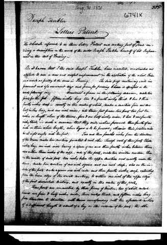
The schedule referred to in these letters, Patent and making part of these containing a description in the words of the said Joseph Tankler himself of his Improvement in the Art of Pressing—
Be it known that I the said Joseph Tankler have invented, constructed and applied to use a new and useful improvement in the application of the wheel, pinion and crank or pulley to the press in Pressing. The said press containing said improvement and of a convenient size and power for pressing cheese is specified in the words following viz:
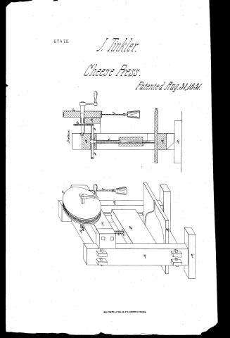
Construct a frame in the following manner, make two pieces for the feet, fifteen inches long two & a fourth inch thick & two & three fourths inches deep—exactly in the center of which, make a mortice five and one half inches long, and one inch wide; into these feet frame two posts two feet ten inches in length clear of the tenons, five & one half inch wide, & two & one fourth inch thick, in such a manner that they will incline forward three fourths of an inch in their whole lengths, where liquor is to be pressed; otherwise their position will be at right angles with the feet. Two and three fourths inches from the shoulder of the tenons make two mortices parallel to each other through each of these posts three inches long, one inch wide leaving a space of one and three fourths inches between them, also within three inches of the upper end of the posts, make two similar mortices, then on the inside of said posts two inches below the upper mortices and exactly under the same, make two mortices of one inch square and one inch deep, also on the inside of the posts, make a groove one inch wide and three fourths inch deep, extending from the lower edge of the small mortices, to within one inch of the upper edge of the first described mortices, and exactly in the center of the posts.
These posts are connected by three pieces of timber, two of which called tenons are five & half inches wide, three inches thick, and fifteen inches long from shoulder to shoulder with tenons corresponding with the aforesaid mortices of a sufficient length to admit of a key on the outside of the posts; the other
Page 3.
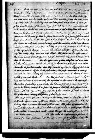
of the same length and width of the beams, one inch thick with tenons corresponding with the small mortises in the posts. — On the front side of each post in the centre thereof, and within six inches of the upper end, is made a mortise three inches long, one inch wide and two inches deep; into these mortises, frame two pieces five & half inches wide, five inches long and two & one fourth inches thick, by tenons projecting from the centre of the under edge of said pieces, and corresponding with said mortises, within one inch of the outer end of each of these pieces, and within three fourths of an inch of each edge, make a mortise through the same of one inch square — let the ends of these two pieces be connected by a piece fifteen inches in length from shoulder to shoulder, five & half inches wide, two inches thick, with two tenons at each end corresponding with the mortises in the pieces last described so as the front side of said pieces may exactly correspond with the end of the aforesaid piece. — Construct a platform fifteen inches wide eighteen inches long, and one inch thick, this fasten on the upper side of the lower beams of the props, so as to project three inches more to the front side than to the rear. On the upper side of said platform cut a circular niche, whose centre should be exactly in the centre of the prop, and whose diameter is fourteen inches, diverting from the regular periphery of said circle, so as to conduct the liquid to the front side of the prop; construct a screw of wrought iron eleven inches long, let nine inches of the same be turned, to seem eighty of an inch thick. On this fast cut a thread eight inches long, one inch round and smooth, the next inch on the same to be square, for the purpose of admitting a cog wheel, the balance projecting above said wheel, must be turned nearly to a point to prevent friction in profiting, which point is placed against a step or plate of iron or steel fastened in the centre of the lower side of the upper beams of the props. — For the purpose of a collar to support the screw, take an iron plate of two & half inches square, one eighth inch thick; in the centre of which is a hole sufficiently large to admit the neck of the screw, this plate is fastened on the upper side of the small piece below the upper beam of the prop, the hole of the collar, to correspond with a hole through the centre of said piece to admit the screw. To this screw is suspended a follower by means of a nut fastened into the upper side of the fifteen inches long
Page 4.
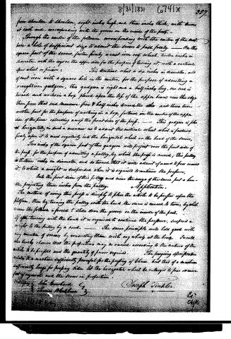
from shoulder to shoulder, eight inches high, and three inches thick; with grooves at each end, corresponding with the grooves on the inside of the posts.
Through the center of the followers corresponding with the center of the screw, bore a hole of sufficient size to admit the screws to pass freely. On the square part of the screws, fasten firmly a cast iron cog wheel, twelve inches in diameter, with the cog on the upper side for the purpose of turning it, with a vertical spur wheel or pinion.
This vertical wheel is six inches in diameter, and of cast iron with a square hole in the center, for the purpose of admitting a wrought iron quignon, this quignon is eight and a half inches long, one end is turned and works in a box placed upon the top of the upper beam near the edge then from that end measure five and half inches towards the other and there turn another part for the purpose of working in a box, fastened in the center of the upper side of the piece extending across the front side of the post. This quignon is placed horizontally in such a manner as to admit the vertical wheel which is fastened firmly upon it to mesh regularly into the horizontal wheel on the head of the screw.
Two inches of the square part of this quignon will project over the front side of the post for the purpose of admitting a pulley, by which the post is moved; this pulley is thirteen inches in diameter, and so turned that it will admit of a cord to pass around it, to which a weight is suspended when it is required to continue the pressure.
Into the front side of this pulley and near the verge of the same put a handle, projecting three inches from the pulley.
Application.
The method of using this press is simply to place the article to be pressed upon the platform, then by turning the pulley with the hand the screw is caused to turn, by which means the follower is forced to slide down the groove on the inside of the post.
If after turning with the hand it is required to continue the pressure, suspend a weight to the pulley by a cord. The same principle will hold good with any number of screws by connecting them with cog wheels at the head.
It will also hereby observe that the proportion may be varied according to the nature of the article to be pressed and the quantity of power required.
The foregoing specification relates to a machine sufficiently powerful for the pressing of brass, but that of a machine sufficiently large for pressing cider let the horizontal wheel be enlarged to four or more feet of girth and the screws in proportion.
Witnesses: John Burkhart 2 Thomas Middleton 3
Joseph Vinkler.
Published accounts: journal notice
Notice in the monthly list of patents
Journal of the Franklin Institute, new ser., vol. 9 (1832), p. 135 · View the page
63. For an improvement in the Application of the Wheel, Pinion and Crank, or Pulley, to the Screw in Pressing; Joseph Tickler, Massillon, Stark county, Ohio, August 31.
About this record
- Patentee
- DATAMP
- Date
- the Name and Date index of patents, DATAMP, USPTO records
- Invention
- DATAMP
- Listed in
- the Name and Date index of patents, DATAMP, USPTO records, Jim Shaw's X-patent list, the Journal of the Franklin Institute, Burke's List of Patents (1847)
- The Franklin Institute's journal spells the name differently.
- Burke's 1847 Patent Office list gives the same patent.