

Drawings and documents
USPTO scan
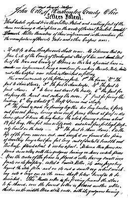
The patent as scanned by the USPTO
-
 Page 1
-
 Page 2
-
 Page 3
-
 Page 4
-
 Page 5
-
 Page 6


U.S. Patent and Trademark Office · Google Patents
Show the transcription Hide (1,795 words)
Machine transcription (LightOnOCR) of the pages as scanned by the USPTO, most of them the handwritten copies made when the records were restored after the 1836 fire. Not checked; it can misread handwriting, so compare it with the scan.
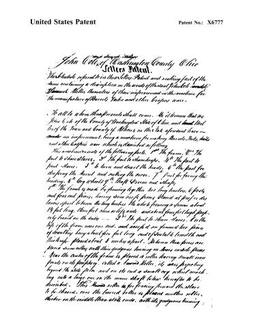
Page 2.
United States Patent
Patent No.: X6777
John Cole, of Washington County Ohio
Letters Patent.
The Schedule referred to in these Letters Patent and making part of the same containing a description in the words of the said Schedule, namely:
Samuel Miller, himself, of their improvement in the machine for the manufacture of Boards, Yards and other Coopers ware.
To all to whom these presents shall come. We it known that we John Cole of the County of Washington State of Ohio, and Samuel Miller of the Town and County of Athens in the State aforesaid have made an instrument, being a machine for making Boards, Yards, Bails and other Coopers ware which is described as follows.
This machine consists of the following parts. 1st The frame. 2nd The part to share Slaves. 3rd The part to share sheeps. 4th The part to joint Slaves. 5th to turn and draw the heads. 6th The part for dressing the Board and cutting the cross. 7th part for facing the heading. 8th Cog wheels 9th Shaft Screw and shafts.
1st The frame is made by joining together two long timbers, 6 feet and four and pieces, having been in six pieces, placed at proper distances apart between the long timbers, the whole forming a frame about 14 feet long, three feet more or less wide, and about four feet high properly braced on the sides.
2nd The part to share Slaves. At the top of the frame near one end, and across it are framed two pieces of scantling being about five feet long and of suitable breadth and thickness, placed about 3 inches apart. Between these pieces are placed seven rollers with thin gutters running in boxes inside pieces. Near the centre of the frame is placed a roller having small iron points on its periphery, called a bearded roller, its axis projecting beyond the side pieces and on its end a small cog wheel meshing into a large one on the main shaft below hereafter to be described. This bearded roller is for forcing forward the Slaves to be shared, over the bearded roller is placed another roller, thicker in the middle than at its ends, with its gutters running
Page 3.
United States Patent
Patent No.: X6777
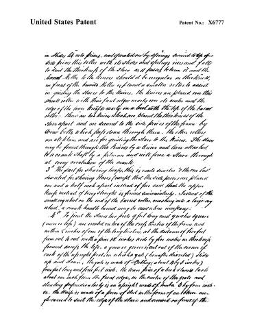
in Slides, let into pieces, and operated on by springs secured to top of side pieces, this roller with its slides and springs rises and falls to cut the thickness of the Slaves as it passes between it and the Burned Roller. In the knives should it be irregular in thickness, in front of the burned Roller is placed a smaller roller to assist in guiding the Slaves to the knives. The knives are placed over this small roller with their front edges nearly over its center and the edge of the lower knives nearly on a level with the top of the burned roller. There are two knives which are placed the thickness of the Slaves apart and are secured to the side pieces of the frame by screw bolts, which pass down through them. The other rollers are all plain and are for guiding the Slaves to the knives. The Slaves may be forced through the knives by a knife and lever attached to a crank shaft by a fulcrum and will force a Slave through at every revolution of the crank.
3. The first for shaving loops. This is made similar to the one last described for shaving Slaves (except that the side pieces are placed one and a half inch apart instead of five and that the upper knife instead of being straight is formed semicircularly. Instead of the small cogwheel on the end of the burned roller meshing into a large cog wheel, a crank handle turned may be used where necessary.
4. To join the Slaves two posts 9 feet long and 9 inches square (more or less) are erected on two of the cross timbers of the frame and within 5 inches of one of the long timbers, at the distance of five feet from end to end with a piece 12 inches wide by five inches in thickness framed across the top, a guinea groove is cut out of the center of each of the upright posts in which a gate (hereafter described) slides up and down; the gate is made of 2" x 3" (about 4 by 5 inches) four feet long and four feet wide, the lower piece of which stands back about one inch from the front edge, in the center of the gate and standing perpendicularly is an upright made of lumber 3 by four inches. The knife is made of a piece of steel in the form of an ellipse and grooved to suit the edge of the Slaves and secured on front of the
Page 4.
United States Patent
Patent No.: X6777
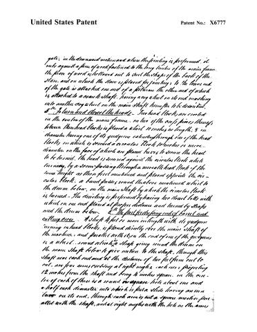
gate; in the downward motion and when the printing is performed, it rubs against a piece of wood fastened to the long limbs of the main frame. The piece of wood is hollowed out to suit the shape of the back of the slave, and on which the slave is placed for joining to the lower end of the gate is attached one end of a pitman the other end of which is attached to a crank shaft, having a cog wheel on its end meshing into another cog wheel on the main shaft hereafter to be described.
5th To turn and close the heads
Two head blocks are erected in the centre of the main frame, on two of the cross pieces thereof, between these head blocks is placed a wheel 10 inches in length; 8 inches diameter having one of its gudgeons extending through one of the head blocks, on which is secured a circular block 10 inches or more diameter, on the face of which are placed bars to secure the head to be turned. The head is secured against the circular block while turning, by a screw passing through a movable head block of the same height as those first mentioned and placed opposite the circular block. A band passes round the above mentioned wheel to the drum below, on the main shaft by which the circular block is turned. The driving is performed by having two stout belts with wheel on one end placed at proper distance and turned by straps and the drum below.
6th The shaft for the spring ends of panel and cutting arms
A shaft 4 feet or more in length with its gudgeons turning in head blocks, is placed directly over the main shaft of the machine, and parallel with it; on the end of one of the gudgeons is a wheel, round which a shaft going round the drum on the main shaft below to give motion to the shaft, through this shaft near each end and at the distance of two feet from each end, are four arms crossing at right angles, each one projecting 12 inches from the shaft and being 4 inches square. In the centre of each of these is a round or square hole about one and a half inch diameter into which is fitted a slide having an iron bar on its end, through each arm is cut a square motion, parallel with the shaft, and at right angles with the hole in the arms.
Page 5.
United States Patent
Patent No.: X6777
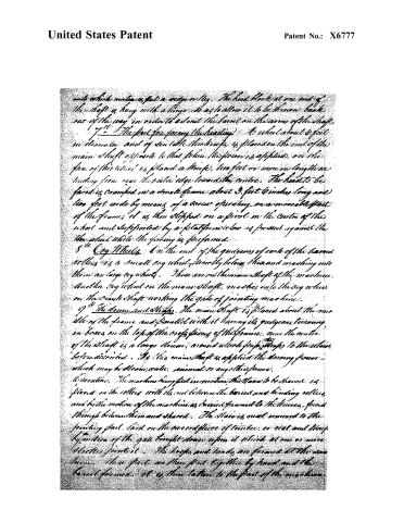
onto which motion is put a wedge or key. The head block at one end of the shaft is hung with a hinge, so as to allow it to be thrown back out of the way in order to admit the barrel on the arms of the shaft.
7. The part for facing the heading. To which about 6 feet in diameter and of very little thickness, is placed on the end of the main shaft opposite to that where the power is applied, on the face of this wheel is placed a knife, two feet or more in length extending from near the outer edge toward the centre. The head to be faced is cramped in a small frame about 3 feet 6 inches long and two feet wide by means of a screw operating on a moveable part of the frame; it is then slipped on a pivot in the centre of the wheel and supported by a platform below is pressed against the the wheel while the facing is performed.
8. Cog Wheels. On the end of the guides of each of the barrel rollers is a small cog wheel directly below these and meshing into them are large cog wheels. These are on the main shaft of the machine. Another cog wheel on the main shaft, meshes into the cog wheel on the crank shaft working the gate of joining machine.
9. The drum and straps. The main shaft is placed about the middle of the frame and parallel with it having its guides, tearing in boxes on the top of the cross pieces of the frame. near the centre of the shaft is a large drum, around which pulleys straps to the strain below described. To this main shaft is applied the driving power which may be steam, water, animal or any other force.
Operation. The machine being put in motion, the slave to be shaved is placed on the rollers with its end between the barrel and binding rollers and by the motion of the machine is driven forward to the knives, forced through between them and shaved. The slave is next removed to the joining part laid on the cross piece of timber, or net, and kept by motion of the gate brought down upon it which at one or more places joins it. The loops and bands are formed at the same time. These parts are then put together by hand and the barrel formed. It is then taken to the part of the machine.
Page 6.
United States Patent
Patent No.: X6777
for shaping the end and acting the edge, which is done by placing it over the arms of the shaft and drawing up the wedges or keys, which force out the slides with their points which secure the barrel in its place while doing the work.
What we claim as our invention and which we wish to secure by letting Patent is the above described machine for making Barrels, Fubs and other copper's ware.
In testimony whereof we have hereunto subscribed our names before two witnesses, and made oath to the same this sixth day of September 1831.
Wilbur
Anna Curtis
Nellie Curtis
John Cole
Samuel Miller
(1833 mms)
(Granted September 29, 1831)
Published accounts: journal notice
Notice in the monthly list of patents, with remarks
Journal of the Franklin Institute, new ser., vol. 9 (1832), p. 173 · View the page
38. For a Machine for the Manufacture of Barrels, Tubs, and other Cooper's ware; John Cole, of Belpree, Washington county, and Samuel Miller, of Athens, Athens county, Ohio, September 29.
Remarks. This machine is intended to perform the various operations of shaving the staves and hoops, jointing the staves, turning and dowelling the heads, dressing the ends of barrels, cutting the croes, and facing the heading. Any adequate power is to be applied to give motion to the machinery, through the intervention of cog wheels, drums, and other gearing. Three are to be fixed cutters through which the staves, or hoops, are to be forced by rollers. The jointing is to be effected by means of a knife, somewhat in the shape of a V, but with a much more obtruse angle; this knife is to be bent into the proper curve, and fixed across a frame working in cheeks like a saw frame; the stave is to be held down upon a suitable bed piece, and is then jointed by the descent of this knife, which must be equal in length to that of the stave. Such a knife, applied to the same purpose, formed a principal feature in a patent noticed by us a few months since. The part part for shaping the heads, is a kind of lathe; and the dressing the ends of the barrel, and forming the croes, is also effected by revolving cutters. The claim is to "the above described machine," which would be very well was it new in all its parts, but this is not the case.
DATAMP: illustration
Illustrations from DATAMP
DATAMP (Directory of American Tool and Machinery Patents), via the Internet Archive · Archived DATAMP page
About this record
- Patentee
- DATAMP
- Date
- the Name and Date index of patents, DATAMP, USPTO records
- Invention
- DATAMP
- Listed in
- the Name and Date index of patents, DATAMP, USPTO records, Jim Shaw's X-patent list, the Journal of the Franklin Institute, Burke's List of Patents (1847)
- Burke's 1847 Patent Office list gives the same patent.