

Drawings and documents
National Archives restored drawings: drawing
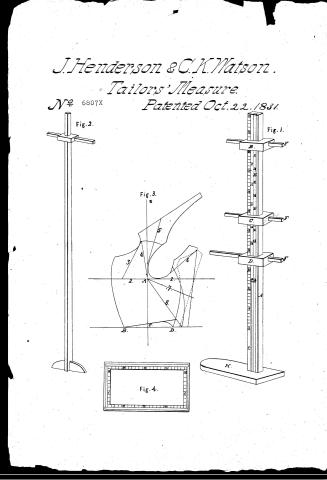
James Henderson and Cooper K. Watson's Patent Drawing for a Measure for Cutting Garments

National Archives, Restored Patent Drawings (Record Group 241) · Full-size scan at the National Archives · Catalog record
Show the text on the drawing Hide (50 words)
Words on the drawing as machine-read by the National Archives; not checked. Useful mainly for searching.
JAMES HENDERSON, & COOPER K. WATSON'S / /2- / MEASURE, FOR CUTTING GARMENTS. / Patented / J. / 6807 / DIVISIÓN. / B. / Fig. / 2. / Fig. / 1. / [38] 38 Tailors' Measures. / 73. MEASURING INSTRUMENTS. / Fig. 3. / F. / C. / <0 / D. / F. / 1. / OF. / B. / D. / H. / Fig 4. / влз
USPTO scan
The patent as scanned by the USPTO
-
 Page 1
-
 Page 2
-
 Page 3
-
 Page 4


U.S. Patent and Trademark Office · Google Patents
Show the transcription Hide (1,286 words)
Machine transcription (LightOnOCR) of the pages as scanned by the USPTO, most of them the handwritten copies made when the records were restored after the 1836 fire. Not checked; it can misread handwriting, so compare it with the scan.
Page 1.
J. Henderson & C.K. Watson.
Tailors' Measure.
No. 6807X Patented Oct. 22, 1831.
Fig. 1.
Fig. 2.
Fig. 3.
Fig. 4.
Page 2.
6807X
Oct 22, 1831
James Henderson & Cooper R. Watson, Zanesville Ohio
Letters Patent
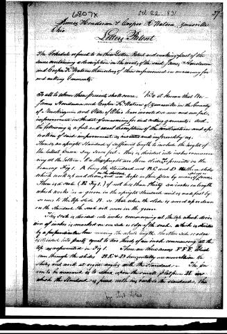
The Schedule referred to in their Letters Patent and making part of the same containing a description in the words of the said James Henderson and Cooper R. Watson themselves of their improvement in measuring for and cutting Garments.
To all to whom these presents shall come: We do it known that We James Henderson and Cooper R. Watson of Zanesville in the County of Washington and State of Ohio have invented a new and useful improvement in the art of measuring for and cutting garments; and the following is a full and exact description of the construction and operation of said improvement as invented and improved by us.
There is an upright Standard of sufficient length to include the height of the tallest person say seven feet. This is divided into inches commencing at the bottom. On this upright are three slides as represented in the drawing Fig 1. A being the Standard and B, C and D the three slides which work up and down on the Standard. These slides are kept in their place by means of springs. There is a scale (as Fig 1) of not less than thirty six inches in length which works in a groove in the upright Standard and is made fast by screws to the top slide B, so that when the slide is moved up or down on the Standard the scale will move in the groove.
This scale is divided into inches commencing at the top which division of inches is marked on one side or edge of the scale, which is divided by a perpendicular line running the whole length. The other side or edge is divided into parts equal to two thirds of an inch commencing at the top as represented in Fig 1. There are three screws F F F which run through the slides B, C & D horizontally are movable in the slides and work at right angles with the Standard. The person to be measured is to stand upon the small platform H on which the Standard is fixed with his back to the Standard. The
Wm. J. A. T.
Page 3.
6807x Oct 22, 1831
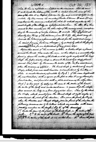
Slide B then is replaced or shifted on the standard that its arm F will touch the bottom of the neck or socket bone, the arm of the arm of the slide D is inserted between his legs and marked upright in the circle. By this means the number of inches between B and D are marked on the moving scale at the slide D which number is the exact length of the body in a perpendicular line. The slide C is then moved to that number on the other edge of the moving scale, corresponding to the number of inches between B and D. That is a point at exactly two thirds of the distance from B to D. This point may be termed the balancing or permanent point for the waist and may be varied from any fashioning changes by a scale by which the proper variation may be made for an individual of any given size.
Before thus much of the measure is taken, a leather strap is placed around the breast, close under the arms, on this strap is a movable strap passing down the centre of the back and at right angles with the breast strap the perpendicular strap is drawn to the waist by a strap placed around that point. By this means the centre of the back is ascertained when the measure is applied. The breast strap is sustained by small straps which pass over each shoulder and are fastened by buckles or slides, a small standard (represented by Fig 2) of the same height with the one described (with a square at the foot so that it may stand) perpendicular, and provided with a slide and arm as the other standard) is then used by applying the arm to the centre of the breast, the centre of the back and under each arm, to ensure that the straps pass around the body in a true horizontal line. Then by the shoulder straps which must join the breast strap at right angles is ascertained the point of the shoulder. Then from the point A Fig 3, where the shoulder and breast straps join in front of the shoulder the following measures are to be taken which are marked with corresponding numbers on the draft (Fig 3 of the drawings)
1st. Under the arm to the point on the breast strap in the centre of the back.
2nd. to the centre of the breast.
3rd. From the centre of the breast to the point.
4th. From the point to the centre of the back at the socket bone.
5th. From the point
Page 4.
6807x
Oct 22, 1831 39
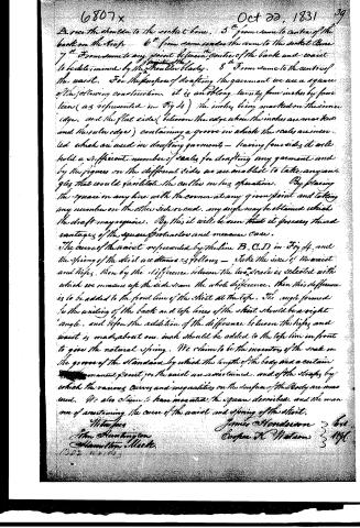
A over the shoulder to the socket bone. 5" from same to centre of the back on the top. 6" from same under the arm to the socket bone. 7" from same to any point between centre of the back and waist to be determined by the shoulder blades. 8" from same to the centre of the waist. For the purpose of drafting the garment we use a square of the following construction. It is an oblong twenty-four inches by fourteen (as represented in Fig 4) the inches being marked on the inner edge, and the flat side (between the edge where the inches are marked and the outer edge) containing a groove in which the scales are inserted which are used in drafting garments—having four sides it will hold a sufficient number of scales for drafting any garment and by the figures on the different sides we are enabled to take any angles that would facilitate the cutter in his operation. By placing the square on any line with the corner at any given point and taking any number on the other side or end, any angle may be obtained which the draft may require. By this it will be seen that it possesses the advantages of the square for tailor and measure case.
The curve of the waist represented by the line B.C.D in Fig 4, and the spring of the skirt are determined as follows—Take the size of the waist and hips, then by the difference between the two, scale is selected with which we measure up the side seam the whole difference, then this difference is to be added to the front line of the skirt at the top. The angle formed by the uniting of the back and top lines of the skirt should be a right angle, and before the addition of the difference between the hips and waist is made about one inch should be added to the top line in front to give the natural spring. We claim to be the inventors of the scale on the groove of the standard by which the length of the body and a certain permanent point for the waist are ascertained, and of the straps by which the various curves and inequalities on the surface of the body are measured. We also claim to have invented the square described, and the manner of ascertaining the curve of the waist and spring of the skirt.
Witnesses
John Huntington
Hamilton Meek
James Henderson 3 6th
Casper H. Watson 3 11th
DATAMP: illustration
Illustrations from DATAMP
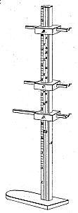

DATAMP (Directory of American Tool and Machinery Patents), via the Internet Archive · Archived DATAMP page
About this record
- Patentee
- DATAMP
- Date
- the Name and Date index of patents, DATAMP, USPTO records
- Invention
- DATAMP
- Listed in
- the Name and Date index of patents, DATAMP, USPTO records, Jim Shaw's X-patent list, Burke's List of Patents (1847)
- Burke's 1847 Patent Office list gives the same patent.