

Drawings and documents
National Archives restored drawings: drawing
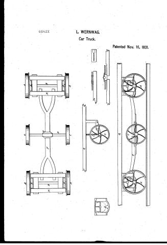
Lewis Wernwag's Patent Drawing for a Railroad Car

National Archives, Restored Patent Drawings (Record Group 241) · Full-size scan at the National Archives · Catalog record
Show the text on the drawing Hide (97 words)
Words on the drawing as machine-read by the National Archives; not checked. Useful mainly for searching.
105. / Railway Rolling Stock, / Trucks, Six Wheel, / Curve Adjusters, / Axles, Radial. / LEW / ERNWAG'S / RAIL / ROAD CAR. / Patented 16th Nov 1831 / CLASSIFICATION / 6842 / A. / C. / DIVISION. / L. / E. / F. / K. / B. / D. / L. / A. / C. / A. / Pat. nov. 16 1831 / G. / no / C. / G. / C. / 17. / A. / REFERENCES. / A, Flange wheels. B, Axles of ditto. C, Regulating wheels. D, Axle of ditto. E, Metal box in the centre, / F, Coupling, or guiding pole. G, Frame. H, Lever, with moveable joint I, Chain. K, Hounds. L, Friction wheels.
USPTO scan
The patent as scanned by the USPTO
-
 Page 1
-
 Page 2
-
 Page 3
-
 Page 4


U.S. Patent and Trademark Office · Google Patents
Show the transcription Hide (919 words)
Machine transcription (LightOnOCR) of the pages as scanned by the USPTO, most of them the handwritten copies made when the records were restored after the 1836 fire. Not checked; it can misread handwriting, so compare it with the scan.
Page 1.
6842X
L. WERNWAG.
Car Truck.
Patented Nov. 16, 1831.
Page 2.
Nov 16, 1831
Lewis Monnag
Harpsensy Virginia
Patent
6842X
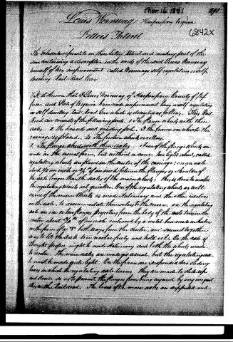
The Schuylers refer to in their Letter Patent and making part of the same containing a description in the words of the said Lewis Monnag himself of his improvement called Monnag self regulating self steering Rail Road Car.
It is known that the Lewis Monnag of Harpsensy County of Jefferson and State of Virginia have made improvement being a self regulating or self steering Rail Road Car which is described as follows. This Rail Road Car consists of the following parts. 1. The flange wheels with their axles. 2. The housings and guiding pole. 3. The frame on which the carriage is placed. 4. The friction wheels or rollers.
1. The flange wheels with their axles. Four of the flange wheels are made in the usual form, but without a cone. Two light wheels, called regulating wheels are placed on the centre of the carriage, on an axle about 1/2 an inch or 3/4 of an inch between the flanges or shoulders of the axle longer than the axles of the main wheels. This is done to make the regulating wheels act quicker. One of the regulating wheels as well as one of the main wheels is made stationary and the other revolves on the axle, to accommodate themselves to the curve. On the regulating axle are one or two flanges projecting from the body of the axle towards the centre about 3/4" of an inch embraced by a metal box made in halves in the form of a T both ways from the centre, and screwed together so as to let the axle be cooler freely and hold oil. On the axle if thought proper might be made stationary and both the wheels made to revolve. The main axles are made as usual, but the regulating axle must be made quite light. On the frame are suspended two sliding boxes in which the regulating axle turns. They are made to slide up and down so as to prevent the flanges from being injured by any irregularities in the rail road. The boxes of the main axles are supported and
Page 3.
The axle, then, the usual way—2. The Guide and guiding Pole. These are made as usual in a common wagon. The guiding or guiding pole is made in two equal parts, and secured by little bolts to the box before mentioned in an oblong notches or notches with holes in the same place in the T about 1/2 inch apart to admit of a bolt for determining the quickness or slowness of the force in regulating the carriage in the curve according to the desire of the conductor of the carriage—3. The frame on which the carriage is placed. This may be made curved or straight in the usual mode and of any convenient length. On the axle of this frame is hung a bar with a movable joint. The bar is of any convenient length and strength. On the end of this bar is a metal box which embraces the middle axle tree at each end in which it moves or slides and always and will keep the main axle in a proper position for forming the curve. The bar embracing the end of the axle tree may be hung with a chain from the frame so that the regulating wheel may be stationary in a straight line and the flange only touch the iron rail when it is required to move in a curve—4. The friction wheels or rollers. Just so, all friction wheels are placed at each end of the carriage under the bolster to make the regulating part more easy. Any kind of friction rollers for the main axle to turn in may be used at pleasure. Operation: When the Rail Road is straight then the wheels all move parallel to each other, but when the carriage comes to go in a curve the flange of the regulating wheel comes in contact with the iron rail and instantly throws the centre of the guiding pole out of a straight line and then aids the four and hind axle trees and keeps them to the centre of the radius of the curve of the curve. Thus moving the carriage in its course without any additional force and without any injury to the rails. As the wheels can be placed any convenient distance apart and the carriage made of any length, long distances or any number of passengers can be moved without inconvenience. What I claim as my invention and wish to be secured by letter Patent is the before described method of making Rail Road carriages with self-regulating or self-guiding wheels and axle, however affixed, the type described.
Page 4.
principle for guiding Rail Road carriages may also be applied to locomotive Engines in the Railroads and other Roads by means of track or Union Railings and rails, or by any other means adapted to the purpose. For a further illustration of my invention I refer to the models and drawings of the same deposited in the Patent Office. In testimony whereof I have hereunto subscribed my name before me witnesses at the City of Washington this 10th day of November 1831.
Witnesses:
William H. Elliot
Chas. M. Keller
Louis Mannag
About this record
- Patentee
- Jim Shaw's X-patent list
- Date
- the Name and Date index of patents, USPTO records, Jim Shaw's X-patent list
- Invention
- the Name and Date index of patents
- Listed in
- the Name and Date index of patents, USPTO records, Jim Shaw's X-patent list, Burke's List of Patents (1847)
- Burke's 1847 Patent Office list gives the same patent.