

Drawings and documents
National Archives restored drawings: drawing
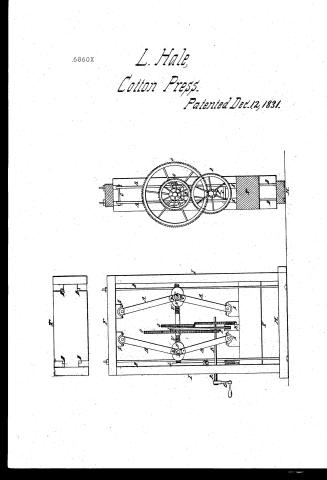
L. Hale's Patent Drawing for a Toggle-joint Screw Press

National Archives, Restored Patent Drawings (Record Group 241) · Full-size scan at the National Archives · Catalog record
Show the text on the drawing Hide (121 words)
Words on the drawing as machine-read by the National Archives; not checked. Useful mainly for searching.
100. PRESSES. / Baling, / Toggle-Joint. / Pressept / Vol.12. nage. 463. / $n 50 / $20 / L LHALE E / CLASSIFIC ATION / 6860 X / Foggte-joint screwprefs / Patented 12 Dec 183/- / DIVISION. / Patented Dec 12-1831 / no number / A. Toğöle-bars. or double bars / B. Square-bar / C. Bolts passing throug doublebars &. boxes / D. Bolts securing Frame / E. P . Hinges / F! Beam / G. Crank / H. Bed-nerce / I. Frame / K. Flanges or hollow Studs / I. Stings / M. Staple orbridge / with / N. Nuts / 0. Dentated-wheels / P. Wheels mashing into Dentated Wheels / R. Crank arbor / S. Boxes / T. Plattin / V. Rightand Lest screw / 36 / Patent office teb / Made under the direction the commyn / of Patent in conformely with who March / Hrinkland Del / Menny / Commyspooner
USPTO scan
The patent as scanned by the USPTO
-
 Page 1
-
 Page 2
-
 Page 3
-
 Page 4


U.S. Patent and Trademark Office · Google Patents
Show the transcription Hide (1,111 words)
Machine transcription (LightOnOCR) of the pages as scanned by the USPTO, most of them the handwritten copies made when the records were restored after the 1836 fire. Not checked; it can misread handwriting, so compare it with the scan.
Page 1.
6860X
L. Hale,
Cotton Press.
Patented Dec. 12, 1831.
Page 2.
Dec 12 1831
Luke Hale, of Hills, State of New Hampshire
Letters Patent.
The schedule referred to in these Letters Patent and making part of the same containing a description in the words of the said Luke Hale himself of his improvement in the standing Prop, called the "Toggle joint screw Prop."
To all persons to whom these presents shall come,
Luke Hale, of Hills, County of Hillsborough and State of New Hampshire,
Mechanic, sends greetings.
Be it known that I Luke Hale have invented constructed made and applied to use a new and useful improvement in the standing Prop, called the Toggle joint screw prop which I specify and describe in my own words viz.
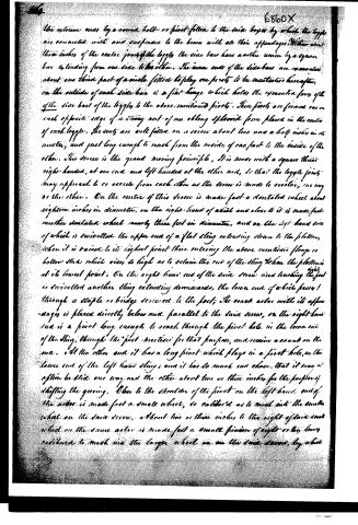
The said Prop for common use is about eight feet high, four and a half feet wide, and one and a half feet deep; the bed piece about twelve inches, and the foot four and a half inches thick. The feet are framed into the bed piece and beams by double tenons well fitted to double mortises, made in the bed piece and beams, into which mortises the tenons are forced and then confined by four iron bolts passing up through the bed piece and beams having strong heads on the lower end, and strong nuts screwed on the upper end of each bolt. These bolts bind the Prop firmly together.
The platter is in length and breadth equal to the width and depth of the frame, and about one foot thick. It has a tenon on each end, exactly fitted so as to slide up and down between the said iron bolts which serve for guides to the platter as well as for efficient supports to resist the power of the prop.
There are four boxes having half round grooves to receive the heads of the toggles, two of which are made fast to the under side of the beams, and the upper two to the upper side of the platter. They are placed at such distances from the ends as to render the power of the toggles as equal as possible on every part of the beam and platter.
On the left hand box on the platter is a flange rising about three or four inches high to guide the lower end of a sling to be described. Each box has a cap with half round grooves matching the grooves in the box, the caps are made fast to the boxes by bolts or screws.
I use two toggle joints in opposite positions between the beam and platter, they are made wide with double bars. The bars are connected at
Page 3.
The extreme ones by a second bolt or pivot fitted to the side bars by which the legs are connected with and suspended to the beam with all their appendages. Within about three inches of the centre joints of the legs, the side bars have another union by a square bar extending from one side to the other. The inner ends of the side bars are excavated about one third part of a circle fitted to play on pivots to be mentioned hereafter. On the outside of each side bar is a flat flange which holds the excavated face of the side bars of the legs to the above-mentioned pivots. These pivots are formed one on each opposite edge of a strong nut of an oblong ellipsoid form placed in the centre of each leg. The nuts are well fitted on a screw about two and a half inches in its diameter, and just long enough to reach from the inside of one part to the inside of the other. This screw is the grand moving principle. It is made with a square thread right-handed, at one end and left-handed at the other end, so that the leg joints may approach to or recede from each other as the screw is made to revolve, one way or the other. On the centre of this screw is made fast a dentated wheel about eighteen inches in diameter, on the right-hand of which and close to it is made fast another dentated wheel nearly three feet in diameter, and on the left hand side of which is swivelled the upper end of a flat sling extending down to the platform, when it is raised to its highest point there entering the above-mentioned flange or hollow stud which rises so high as to retain the end of the sling when the platform is at its lowest point. On the right-hand end of the said screw near touching the foot is swivelled another sling extending downwards, the lower end of which passes through a staple or bridge screwed to the foot; The crank arbor with its appendages is placed directly below and parallel to the said screw, on the right-hand end is a pivot long enough to reach through the pivot hole in the lower end of the sling, through the foot provided for that purpose, and receiving a crank on the end. At the other end it has a long pivot which plays in a pivot hole in the lower end of the left-hand sling; and it has so much end chance, that it may at option be slid one way and the other about two or three inches for the purpose of shifting the gearing. Close to the shoulder of the pivot on the left-hand end of the arbor is made fast a small wheel, so calibrated as to mesh into the smaller wheel on the said screw, about two or three inches to the right of said small wheel on the same arbor is made fast a small pinion of eight or ten turns calibrated to mesh into the larger wheel on the said screw, by which
Page 4.
6860X
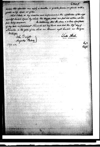
means the operator can apply a smaller or greater power, or operate with a greater or less speed at option.
That I claim as my invention and improvement, is the application of the right and left-handed levers by which the toggle joints are put into action, all other parts being common.
In testimony that the above is a true specification of my said improvement I hereunto set my hand and seal this 29th day of November in the year of our Lord one thousand eight hundred and thirty-one.
Witnesses,
John Dwight
Augustus Peabody
Luke Hale
1190
Ex. 4
ClyW.
Published accounts: journal notice
Notice in the monthly list of patents, with remarks
Journal of the Franklin Institute, new ser., vol. 9 (1832), p. 391 · View the page
7. For a standing press, called the Toggle Joint Screw Press; Luke Hall, Hollis, Hillsborough county, New Hampshire, December 12.
Remarks. In this press there are two toggle joints, which, when the pressure is taken off, recede from each other, and when it is to be exerted, are drawn towards each other until the compound bars of which each toggle joint consists stand in parallel lines. In order to draw them towards each other, the shaft of a strong screw passes through nuts properly fixed in the middle of each toggle joint, this shaft having a right handed screw at one end, and a left handed screw at the other, acts simultaneously on the joints to cause them either to approach or recede. The screw is to be turned by a crank, on the shaft of which there is a pinion taking into a wheel on the screw shaft, and capable therefore of operating upon it with vast power. The claim is to the application of the right and left handed screw to the toggle joints, all the other parts being common. The press, as represented, will certainly be a very powerful one, but we apprehend that there are but very few purposes to which it can be applied. The range of its platten will be small, and its action slow; and, for most purposes, these circumstances would entirely neutralize its good properties.
About this record
- Patentee
- Jim Shaw's X-patent list
- Date
- the Name and Date index of patents, USPTO records, Jim Shaw's X-patent list
- Invention
- the Name and Date index of patents
- Listed in
- the Name and Date index of patents, USPTO records, Jim Shaw's X-patent list, the Journal of the Franklin Institute, Burke's List of Patents (1847)
- Burke's 1847 Patent Office list gives the same patent.