

Drawings and documents
USPTO scan
The patent as scanned by the USPTO
-
 Page 1
-
 Page 2
-
 Page 3
-
 Page 4


U.S. Patent and Trademark Office · Google Patents
Show the transcription Hide (1,252 words)
Machine transcription (LightOnOCR) of the pages as scanned by the USPTO, most of them the handwritten copies made when the records were restored after the 1836 fire. Not checked; it can misread handwriting, so compare it with the scan.
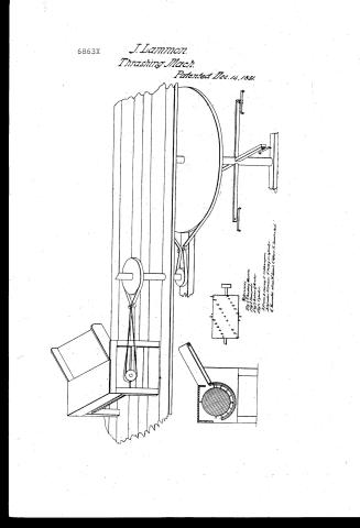
Page 1.
6863X
J. Lammon.
Thrashing Mach.
Patented Dec. 14, 1831.
References:
Fig. 1. Thrashing Machine.
Fig. 2. Hopper.
Fig. 3. Section of Hopper.
Fig. 4. Cylinder.
Fig. 5. Covering.
Fig. 6. Cylinder.
Fig. 7. Hopper.
Fig. 8. Section of Hopper.
Fig. 9. Cylinder.
Fig. 10. Covering.
Fig. 11. Cylinder.
Fig. 12. Hopper.
Fig. 13. Section of Hopper.
Fig. 14. Cylinder.
Fig. 15. Covering.
Fig. 16. Cylinder.
Fig. 17. Hopper.
Fig. 18. Section of Hopper.
Fig. 19. Cylinder.
Fig. 20. Covering.
Fig. 21. Cylinder.
Fig. 22. Hopper.
Fig. 23. Section of Hopper.
Fig. 24. Cylinder.
Fig. 25. Covering.
Fig. 26. Cylinder.
Fig. 27. Hopper.
Fig. 28. Section of Hopper.
Fig. 29. Cylinder.
Fig. 30. Covering.
Fig. 31. Cylinder.
Fig. 32. Hopper.
Fig. 33. Section of Hopper.
Fig. 34. Cylinder.
Fig. 35. Covering.
Fig. 36. Cylinder.
Fig. 37. Hopper.
Fig. 38. Section of Hopper.
Fig. 39. Cylinder.
Fig. 40. Covering.
Fig. 41. Cylinder.
Fig. 42. Hopper.
Fig. 43. Section of Hopper.
Fig. 44. Cylinder.
Fig. 45. Covering.
Fig. 46. Cylinder.
Fig. 47. Hopper.
Fig. 48. Section of Hopper.
Fig. 49. Cylinder.
Fig. 50. Covering.
Fig. 51. Cylinder.
Fig. 52. Hopper.
Fig. 53. Section of Hopper.
Fig. 54. Cylinder.
Fig. 55. Covering.
Fig. 56. Cylinder.
Fig. 57. Hopper.
Fig. 58. Section of Hopper.
Fig. 59. Cylinder.
Fig. 60. Covering.
Fig. 61. Cylinder.
Fig. 62. Hopper.
Fig. 63. Section of Hopper.
Fig. 64. Cylinder.
Fig. 65. Covering.
Fig. 66. Cylinder.
Fig. 67. Hopper.
Fig. 68. Section of Hopper.
Fig. 69. Cylinder.
Fig. 70. Covering.
Fig. 71. Cylinder.
Fig. 72. Hopper.
Fig. 73. Section of Hopper.
Fig. 74. Cylinder.
Fig. 75. Covering.
Fig. 76. Cylinder.
Fig. 77. Hopper.
Fig. 78. Section of Hopper.
Fig. 79. Cylinder.
Fig. 80. Covering.
Fig. 81. Cylinder.
Fig. 82. Hopper.
Fig. 83. Section of Hopper.
Fig. 84. Cylinder.
Fig. 85. Covering.
Fig. 86. Cylinder.
Fig. 87. Hopper.
Fig. 88. Section of Hopper.
Fig. 89. Cylinder.
Fig. 90. Covering.
Fig. 91. Cylinder.
Fig. 92. Hopper.
Fig. 93. Section of Hopper.
Fig. 94. Cylinder.
Fig. 95. Covering.
Fig. 96. Cylinder.
Fig. 97. Hopper.
Fig. 98. Section of Hopper.
Fig. 99. Cylinder.
Fig. 100. Covering.
Page 2.
6863X Dec 14, 1831 771
John Lammom
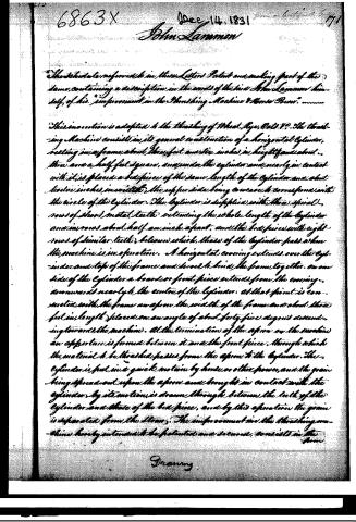
The schedule referred to in these Letters Patent and making part of the same, containing a description in the words of the said John Lammom himself, of his "Improvement in the Thrashing Machine & Horse Power."
This invention is adapted to the thrashing of Wheat, Rye, Oats &c. The thrashing Machine consists in its general construction of a horizontal Cylinder, resting on a frame about three feet and six inches in height and about three and a half feet square, and under the cylinder and nearly in contact with it, is placed a bed piece of the same length of the cylinder and about twelve inches in width, the upper side being concave to correspond with the circle of the cylinder. The cylinder is supplied with three spiral rows of short metal teeth extending the whole length of the cylinder and in rows about half an inch apart, and the bed piece with eight rows of similar teeth, between which, those of the cylinder pass when the machine is in operation. A horizontal covering extends over the cylinder and top of the frame and serves to bind the frame together. On one side of the cylinder a board or front piece extends from the covering, downwards nearly to the centre of the cylinder. At that point is connected with the frame an apron the width of the frame and about three feet in length placed on an angle of about forty-five degrees descending towards the machine. At the termination of the apron on the machine an aperture is formed between it and the front piece, through which the material to be thrashed passes from the apron to the cylinder. The cylinder is put in a quick motion by horse or other power, and the grain being spread out upon the apron and brought in contact with the cylinder by its motion is drawn through between the teeth of the cylinder and those of the bed piece, and by this operation the grain is separated from the straw. The improvement in the thrashing machine hereby intended to be patented and secured, consists in the
Drawing.
Page 3.
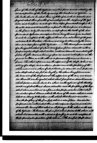
form of the teeth of the cylinder and bed piece, and in altering the set and position of the teeth by moving the bed piece or cylinder. The teeth should be about three eighths of an inch in diameter, and project about three fourths of an inch from the surface of the cylinder and bed piece, and be of a truer taper from their surface to the outer end, and terminate in a point. The bed piece is to please in the frame as by its elevation or depression, the teeth of the bed piece and cylinder, are separated or brought nearly in contact, so as to be adapted to the different kinds and situations of the grain intended to be threshed. The same end may be attained by the elevation and depression of the cylinder. The Horse power consists of a horizontal wheel of about twenty-four feet in diameter with a perpendicular shaft about sixteen inches in diameter, and about eight feet in height, one end turning upon an axis in a bed piece on the ground or floor, and the other in a permanently secured beam or frame. The wheel is placed near the upper end of the shaft. A band consisting of a strap, cord or chain, passes round the periphery of the wheel, and round a whorl of about twelve inches in diameter, on a perpendicular shaft about six feet in length. This whorl being placed near the lower end of the shaft and at the upper end of the beam and connected therewith is a horizontal wheel about four feet in diameter round which passes a similar band to a whorl on the cylinder of the threshing machine, of about three inches in diameter, near the periphery of the large wheel above mentioned are placed two perpendicular rollers about six inches apart between which the band of the main wheel is made to pass on its way to the whorl with which that band is connected. Near the periphery of the four feet wheel is also placed two similar perpendicular rollers about three inches asunder to guide and manner the band of that wheel in its passage to the whorl on the axis of the cylinder. The band on the four feet wheel passes to the whorl with which it is connected with a twist, or by tying so as to be adapted to the perpendicular position of the whorl. The six feet shaft above
Page 4.
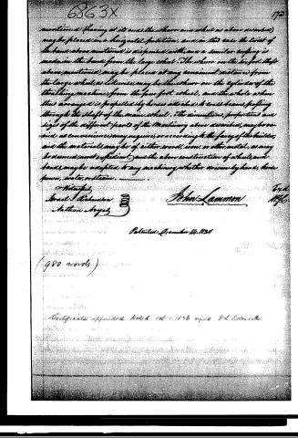
mentioned (having at its ends the whorl and wheel as above described) may be placed in a horizontal position, and in this case the twist of the band above mentioned is dispensed with, and a similar roping is made in the band from the large wheel. The whorl on the six-foot shaft above mentioned may be placed at any convenient distance from the large wheel, as likewise may be the whorl on the cylinder of the threshing machine from the four-foot wheel, and the whole when thus arranged is propelled by horses attached to cross-beams passing through the shaft of the main wheel. The dimensions, proportions and sizes of the different parts of the machinery above described, may be varied as convenience may require, or according to the fancy of the builder, and the materials may be of either wood, iron, or other metal, as may be deemed most expedient, and the above construction of wheels and bands may be adapted to any machinery whether driven by hand, horse power, water, or steam.
Witnesses
Israel Ticknor
Nathan Hayes
John Lammon
Patented December 14, 1831
(980 words)
Certificate appended dated October 1856 signed Wm. Edmonds.
Published accounts: journal notice
Notice in the monthly list of patents, with remarks
Journal of the Franklin Institute, new ser., vol. 9 (1832), p. 392 · View the page
10. For a Thrashing Machine and Horse Power; John Lammon, Macedon, Wayne county, New York, December 14.
Remarks. We are informed by the patentee that the improvement here made in the thrashing machine consists in the form of the teeth of the cylinder and the bed piece; and in allowing these two parts to recede from each other. The teeth are to be tapering, being about threeeighths of an inch in diameter at their lower ends, and terminating in a point. Their length is to be about three-fourths of an inch. The horse power consists of a band wheel upon a vertical shaft, a strap from which turns a whirl on a second shaft, carrying another band wheel, the strap of which drives the cylinder of the machine. There may be novelty in each, but we have not discovered it.
About this record
- Patentee
- the Journal of the Franklin Institute, Journal
- Date
- the Name and Date index of patents, USPTO records, Jim Shaw's X-patent list
- Invention
- the Name and Date index of patents
- Listed in
- the Name and Date index of patents, USPTO records, Jim Shaw's X-patent list, the Journal of the Franklin Institute, Burke's List of Patents (1847)
- The patentee's full name comes from the Franklin Institute's journal.
- Burke's 1847 Patent Office list gives the same patent.