

Drawings and documents
National Archives restored drawings: drawing
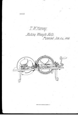
T.W. Harvey's Patent Drawing for a Machine for Making Wrought Nails

National Archives, Restored Patent Drawings (Record Group 241) · Full-size scan at the National Archives · Catalog record
Show the text on the drawing Hide (38 words)
Words on the drawing as machine-read by the National Archives; not checked. Useful mainly for searching.
85. METAL WORKING, / Wrought Nail, Making. / ag / CLASSIFICATION / #6909* / 69.09 X / DIVISION. / T.W.HARVEY'S / MACHINE FOR MAKING WROUGHT NAILS. - / Patented : Jan 24.1832 / OIR
USPTO scan
The patent as scanned by the USPTO
-
 Page 1
-
 Page 2
-
 Page 3
-
 Page 4


U.S. Patent and Trademark Office · Google Patents
Show the transcription Hide (1,023 words)
Machine transcription (LightOnOCR) of the pages as scanned by the USPTO, most of them the handwritten copies made when the records were restored after the 1836 fire. Not checked; it can misread handwriting, so compare it with the scan.
Page 1.
6909X
T. W. Harvey,
Making Wrought Nails,
Patented Jan. 24, 1832
Page 2.
6909X Jan 24, 1852 297
Thomas W. Marry
Letters Patent
The Machine referred to in their Letters Patent and making part of the same containing a description in the words of the said Thomas W. Marry himself of his Improvement in the Machine for making wrought nails.
Be it known that I Thomas W. Marry of Jamestown Schenectady County State of New York have made a new and useful improvement in the Machine for making wrought nails which is described as follows. The Machine may be made wholly of cast and wrought iron and steel, or the frame may be made of wood.
The frame marked A, in the annexed drawing is made about ten feet long, ten feet wide, and two and a half feet high; having an opening B left in the centre thereof, extending nearly its whole length to admit the rollers C, C. hereafter to be described. The scourging rollers or die plates D, D for scourging or rolling out the nails, are made of steel ten inches in diameter and as thick as the required nails. The circumference of each of said scourging rollers or die plates, is divided into ten or more or less equal parts, according to the length of the nails to be rolled or scourged; and each division on the periphery of the scourging roller or die plate, and the corresponding one on the opposite roller or plate are to be filed away and shaped, or indented, in such a manner, that when they come together during the revolution of the scourging rollers or die plates, they will form the spaces or cavities exactly the shape of the nail to be rolled or scourged therein; and there are also the same number of objects E, E, E, as there are divisions, and tails into the peripheries of the scourging rollers or die plates to cut the nails from the rod as fast as rolled; said chisels coming together with their edges, as the scourging rollers or die plates rotate. The scourging rollers or die plates D, D, are secured firmly on the ends of the axles, A, A, hereafter to be described, by rollers F, F, and G, G, having screws H, H, H, passing the rollers F, F, and the scourging rollers or die plates D, D, into the figure rollers G, G, the rollers F, F, being movable, these rollers, besides keeping the scourging rollers or die plates from and free in a vertical position, were able to secure the
D. Marry
Page 3.
the sheets. The smudging rollers or die plates are placed across the centre of the frame and revolve in a vertical position opposite one against each other as shown in the drawing. Side Rollers on the sides of the smudging rollers or die plates and where their peripheries meet are placed two rollers C, C, at right angles to them revolving also in a vertical position with their peripheries nearly in contact, leaving just space enough to form the head of the nail. The smudging rollers or die plates forming the edges head as before described. These rollers are four feet in diameter, the peripheries of which are of cast iron or steel and may be plain or indented. They are supported and turned on axles K, K, in the heads of standards L, L, secured to the frame by screws M, M, and are brought nearer to or farther from each other as occasion may require, by the tempering screws N, N, bearing against the edges of the standards L, L. On the side of one the rollers C, C is formed a cylindrical row of grooves O, into which the pinion P, is inches in diameter placed on the end of axle D, makes, and by which the rollers C, C are turned.
Axles and Cogwheels. On each side of the frame and parallel with each other are placed two axles D, D, supported and turning with their bearings or journals in openings in the heads of standards R, R, R, R. On the ends of said axles, over the centre of the frame, are placed the smudging rollers or die plates as before described, and at the other ends are placed the cogwheels B, B, ten and a half inches in diameter meshing into each other. The standards are all regulated by tempering screws, those of the centre of the frame by the screws T, T, operating on the smudging rollers or die plates. U, U, are cavities in the top of the frame containing water, in which the outer edges of the smudging rollers or die plates revolve, to prevent their becoming heated.
The machine is operated by steam, manual or any known power of plate to the shaft D, on which is represented a crank in the drawing. The rods of iron from which the nails are smudged or rolled are slit of a proper size and heated, then passed perpendicularly through an iron tube or guide created above the machine between the smudging rollers or die plates and these smudging rollers or frames into nails of any shape required.
The proportions and dimensions of the several parts of the before described machine may be varied to suit the different kinds and sizes of nails required.
Page 4.
6909X
the proportions of the side rollers may also be varied.
What I particularly claim as an improvement in the before described machine for making enright nails are the side rollers C, C, and the general arrangement of the gearing. I make no claim to the smearing rollers or die plates.
In testimony that the foregoing is a true description of my said improvement, I have hereunto subscribed my name before two witnesses this 21st day of January 1852.
Witnesses
William G. Cranach
William P. Elliot
Thomas H. Staring
Cont.
N.C.
Published accounts: journal notice
Notice in the monthly list of patents, with remarks
Journal of the Franklin Institute, new ser., vol. 10 (1832), p. 37 · View the page
24. For a Machine for making Wrought Nails; James W. Harvey, Jamestown, Chautauqua county, New York, January 24.
Remarks. The nail rods are to be heated and passed down perpendicularly through a tube, or guide, between two swedging wheels, or rollers, which have indentations on them to form the edges and heads of the nails, and furnished also with chisels which cut them off of proper lengths. These rollers are made of steel, are ten inches in diameter, and of such thickness as the size of the nail may render necessary. On their lower sides they dip into boxes containing water, to preserve them from being too highly heated. The sides of the nails are to be formed by two other iron rollers, or wheels, which revolve at right angles with the swedging rollers. These are to be four feet in diameter, and are to approach each other sufficiently near to determine the thickness of the nail. All these rollers revolve in a vertical position. We shall not now attempt to describe the accessory apparatus for giving motion to the respective parts, as we deem this unnecessary. The claim is to the large rollers or wheels, for forming the sides of the nails; the swedging rollers, or die plates, not being considered as new.
About this record
- Patentee
- DATAMP
- Date
- the Name and Date index of patents, DATAMP, USPTO records
- Invention
- DATAMP
- Listed in
- the Name and Date index of patents, DATAMP, USPTO records, Jim Shaw's X-patent list, the Journal of the Franklin Institute, Burke's List of Patents (1847)
- Burke's 1847 Patent Office list gives the same patent.