

Drawings and documents
National Archives restored drawings: drawing
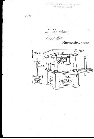
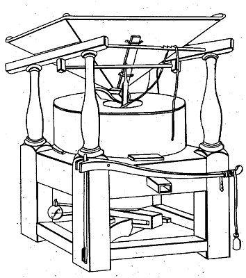
Gideon Hotchkiss' Patent Drawing for a Grist Mill

National Archives, Restored Patent Drawings (Record Group 241) · Full-size scan at the National Archives · Catalog record
Show the text on the drawing Hide (87 words)
Words on the drawing as machine-read by the National Archives; not checked. Useful mainly for searching.
(83) MILLS. / Grinding Mills. / CLASSIFICATION / Disk Action: Horizontal. / 6913 X / $2 / DIV ISION. / #6913x / GIDEON HOTCHKISS / GRIST MILL. / Patented 27Jan 1832. / Fig 3. / Reference / Fig / Top screw, of the spindle / Fig.20°c / balance rind and wings of Flights / Driver, and d' / d' / d° Fig 2 Topview of it / d Pulley / 08 / Lock joint / Lever and weight Fig 3 / Fig 1 / Patent Office 3Nov 1878 / Made under the direction of the Connuipioner / of Patents in conformity with act 3 March 1837 / Comminious of Patents
USPTO scan
The patent as scanned by the USPTO
-
 Page 1
-
 Page 2
-
 Page 3
-
 Page 4
-
 Page 5


U.S. Patent and Trademark Office · Google Patents
Show the transcription Hide (1,140 words)
Machine transcription (LightOnOCR) of the pages as scanned by the USPTO, most of them the handwritten copies made when the records were restored after the 1836 fire. Not checked; it can misread handwriting, so compare it with the scan.
Page 1.
6913X
G. Hotchkiss.
Grist Mill.
Patented Jan. 27, 1832.
Fig. 1
Fig. 2
Fig. 3
Page 2.
Jan 27, 1832
Simon Hotchkiss.
Letter Patent.
The Schedule referred to in these Letters Patent and making part of this stone containing a description in the words of the said Simon Hotchkiss himself of his improvement in the bristle mill.
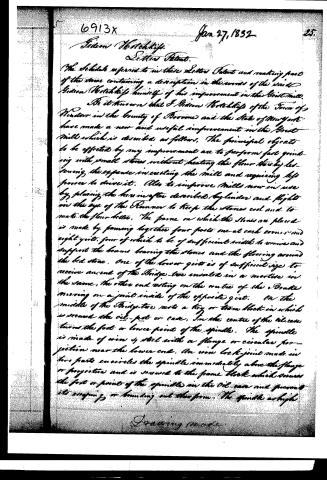
Be it known that S. Simon Hotchkiss of the Town of Windsor in the County of Monroe and the State of New York have made a new and useful improvement in the bristle mill which is described as follows. The principal objects to be effected by my improvement are to perform fast grinding with small stones without heating the flour thereby lessening the expense in erecting the mill and requiring less power to drive it. Also to improve mills now in use by placing the hereinafter described (cylinders) and flights on the eye of the Runner to keep the stones cool and to make the flour better. The frame on which the stones are placed is made by joining together four posts one at each corner and eight girts, four of which to be of sufficient width to receive and support the beams bearing the stones and the flooring around the bed stone. One of the lower girts is of sufficient size to receive an end of the Bridge-tire enlaced in a mortise in the same, the other end resting on the centre of the Brake moving on a joint inside of the opposite girt. On the middle of the Bridge-tire rests a key or iron block in which is secured the oil-pot or case. In the centre of the oil-case turns the foot or lower point of the spindle. The spindle is made of iron & steel with a flange or circular projection near the lower end. An iron lock-joint made in two parts encircles the spindle immediately above the flange or projection and is secured to the frame block which secures the foot or point of the spindle in the oil-case and prevents its swinging or bouncing out therefrom. The spindle as high
Page 3.
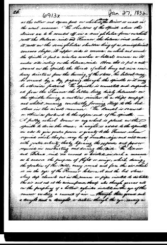
as the collar and square part on which the Driver is made in the usual manner. The shoulders of the spindle above the Driver are to be rounded off in a semi-globular form on which rests the Balance ring and Runner, the balance ring where it rests on the semi-globular shoulder being of a semispherical concave shape, its upper side is concave on which and around the spindle is put a circular washer or lateral concave on its under side resting on the balance ring. Above this is put a nut screwed on the spindle the threads of which being cut in a contrary direction from the turning of the stone, the lateral may be secured by a key passing through the spindle or it may be otherwise fastened. The spindle is connected and suspended from the Runner the latter being highly balanced on the spindle, having a motion similar to a ship's compass and whilst running constantly forming itself to the bed stone in the nicest manner. The damsel is screwed or otherwise fastened to the upper end of the spindle.
A pulley, wheel, drum or cog wheel is placed on the spindle to drive the stone, a weight is added to the spindle in order to give greater power or gravity to the Runner when required which therefore may be of smaller size and will move with greater velocity thereby lessening the expense and power required in constructing and driving the mill. The Driver and Balance ring are curved or twisted in such a manner as to answer the purpose of flights or wings, which, during the operation of the mill, carry round and force the air which is in the eye of the Runner between it and the bed stone along deep channels cut in the runner or pipes inserted to distribute the air and out at the circumference, there also through grooves cut on the periphery of a hollow cylinder inserted on the eye of the runner creating a current of air—through these grooves and a trough and a trough, or motion through the eye, causing a
Page 4.
6913x Jan 27, 1832 2
more free, easy and quick admission of the grain between the stones. The grain on entering the eye comes in contact with two curved wings or projections on the inside of the cylinder before mentioned. When the dust or any other dirt, which may be on the grain is separated from it, and being lighter than the grain is carried by the currents of air through the grooves out from the stones. Mills that grind fast are liable to heat the flour and consequently injure it, but the currents of air, created as before described, and driven between the stones prevent this from taking place. So the brake may be attached as new or lighter stuff in the usual way to raise or sink the Runner at pleasure: also near one end of the brake and on it are placed weights and springs or a fulcrum supporting a lever attached to one of the corner posts of the frame by a bolt passing through one of its ends and having a weight suspended near the other end in the manner of a steel yard by which the gravity or power of the Runner may be increased or diminished at pleasure, so that an equilibrium is formed between the power required and power applied. The Hops, Hopper, Frame, Hopper and Shoe are made in the usual manner. What I claim as my Invention and for which I solicit Letters Patent is increasing the gravity of the Runner by means of weight attached to the spindle or by means of the flange near the bottom of the spindle and the lock joint fastened to the frame block on the Bridge-tie with the lever and weight acting on the same. The spindle passing through the balance-rod secured to and suspended from the Runner, the inserting wings or flights in the eye, the shape of the driver and balance-rod causing currents of air to pass between the stones in pipes or otherwise and through grooves on the circumference of a hollow cylinder placed within the eye of the Runner carrying off the dirt and keeping
Page 5.
28. 6913X Jan 27, 1832
the stones from heating, likewise causing a draft thru the eye which allows the grain to pass more freely to the grinding stones.
Done at the City of Washington this 24th day of January 1832
Witnesses
Wm. G. Branch
Wm. F. Elliot
Simon Footchiff
(1171 wts.)
Patented January 27, 1832.
Published accounts: journal notice
Notice in the monthly list of patents, with remarks
Journal of the Franklin Institute, new ser., vol. 10 (1832), p. 38 · View the page
28. For an improvement in the Grist Mill; Gideon Hutchkin, Windsor, Broome county, New York, January 27.
Remarks. The object aimed at by the patentee, he informs us, is to grind rapidly with small stones without heating the flour; and consequently to lessen the expense of erecting, and the power required for driving such a mill. A quadrangular frame is to be made in the usual way; on the lower end of the spindle there is to be a projecting rim, or flanch, just above its step, or point; a clutch box, catching above this projection, prevents the spindle from rising. The upper stone is to be the runner, which rests, by means of a balance rine, upon the upper end of the spindle; this being formed hemispherical, and the rine hollowed to suit it. Above the balance rine is a collet and nut, which secure the stone from rising. The balance rine and driver are to be so formed as to blow wind into the eye of the stone, by their revolution, and channels, or tubes, are to be made to cause currents of air to pass between the stones. By loading the bridge tree, the stone may be forced down, or the top of the spindle may be weighted for the same purpose. The claims are to increasing the gravity of the runner in either of the ways above named; the inserting wings, or flights; the form given to the driver and balance rine, and the pipes, or channels, for passing currents of air, &c. &c. The particular forms of some of the parts described in the specification, are no doubt new; in other points, however, the present patentee has trenched upon preoccupied ground. The flanch, or button, at the lower end of the spindle, was particularly described in a patent noticed by us sometime since. Stones also have been loaded at top, both by direct weights and by levers; and air holes have been made for the purpose of cooling the flour. The claim, therefore, if good, must rest upon the precise manner adopted by the patentee.
DATAMP: illustration
Illustrations from DATAMP

DATAMP (Directory of American Tool and Machinery Patents), via the Internet Archive · Archived DATAMP page
About this record
- Patentee
- DATAMP
- Date
- the Name and Date index of patents, DATAMP, USPTO records
- Invention
- DATAMP
- Listed in
- the Name and Date index of patents, DATAMP, USPTO records, Jim Shaw's X-patent list, the Journal of the Franklin Institute, Burke's List of Patents (1847)
- Burke's 1847 Patent Office list gives the same patent.