

Drawings and documents
National Archives restored drawings: drawing
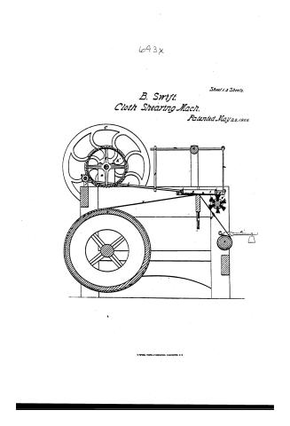
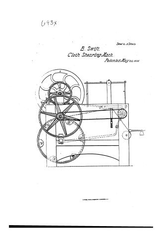
Boriah Swift's Patent Drawing for a Machine for Cloth Shearing


National Archives, Restored Patent Drawings (Record Group 241) · Full-size scan at the National Archives · Catalog record
Show the text on the drawing Hide (202 words)
Words on the drawing as machine-read by the National Archives; not checked. Useful mainly for searching.
Sheet 1. 26. CLOTH. / [37] Sheari / Plats. it. / CLASSIFICATION / 93+ / 693X / Bariah Swift. / DIV ISION. / Cloth Shearing / Vol.2. ps. 109 / Patented Mayes 1806. / Preferences. / Preferences. / a. a short postes / r. 1½ pinion. s. / b. crank shaft. / t. short shaft.uz inch Coswheel. / e balance wheel, / V. so inch eagwheel. w. cylinder. / d. in inch. engiohed. / x cloth. y. shearboard I small cylinder / e 2% inch pinion / a' lear d weight. b' discossating lever / fif studs. / c' hook. d' rad in du cloth e' brush / g.g. 11/4 inch cranks. h. h. rods / f' strop. g 'g' pulleys. of' Iropelling / i upper part of the sliding frame. / pulley α band. / ЛИПА / k under part of the sliding frame / Sig.1. Sideview. J.y.2. Section. / ll, perpendilular zav.m.m. learn. n. hooks. / Tiy.3. Topview. / 0 roller. p. under shear. q. upper shear. / Patent. affice / March5 1845 / made under the direction of the Commisioner / of Patents in conform ty with acto of Congup / March 30 1837 / ns Elloworth / Correct / CVVMKeller, / Comminational Catents
Sheet 2. CLASSIFICATION / 693-+ / DIVISION. / Plate. 3. / Beriah Lwift / Tig. 3 / cloth Thearing Vol.2. / Pat. hay 25. 1806. / h'
Sheet 3. Beridh Lwift. / Plat 2., / CLASSIFICATION / Cloth Thearing Valz. by 109 / 693-4 / Patention hay 25th N. 1826. / DIVISION. / 10 / h' / to / a'
USPTO scan
The patent as scanned by the USPTO
-
 Page 1
-
 Page 2
-
 Page 3
-
 Page 4
-
 Page 5
-
 Page 6
-
 Page 7


U.S. Patent and Trademark Office · Google Patents
Show the transcription Hide (1,267 words)
Machine transcription (LightOnOCR) of the pages as scanned by the USPTO, most of them the handwritten copies made when the records were restored after the 1836 fire. Not checked; it can misread handwriting, so compare it with the scan.
Page 1.
693x
Sheet 1.3 Sheets.
B. Swift.
Cloth Shearing Mach.
Patented May 25, 1806.
A. PETER, PHOTO-LITHOGRAPHER, WASHINGTON, D.C.
Page 2.
693x
Sheet 2. 3 Sheets.
B. Swift.
Cloth Shearing Mach.
Patented May 25, 1806.
R. PETTIE, PHOTO-LITHOGRAPHER, WASHINGTON, D.C.
Page 3.
693X
Sheet 3. 3 Sheets.
B. Swift.
Cloth Shearing Mach.
Patented May 26, 1806.
Fig. 3.
Page 4.
May 25, 1806
Letters Patents.
Spence May 25, 1806.
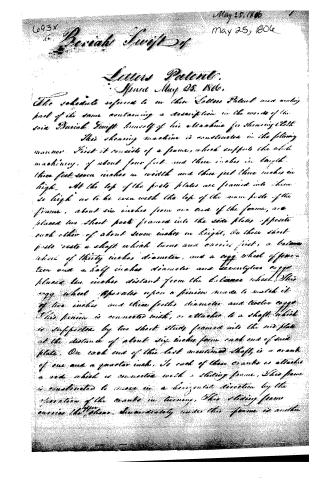
The schedule referred to in this Letters Patent was made part of the same containing a description in the words of the said David Swift himself of his machine for shewing cloth.
This shewing machine is constructed in the following manner. First it consists of a frame, which supports the whole machinery, of about four feet and three inches in length, three feet seven inches in width and three feet three inches in height. At the top of the frame plates are framed into them so high as to be even with the top of the main posts of the frame, about six inches from one end of the frame, are placed two short posts framed into the side plates opposite each other of about seven inches in height, on these short posts rests a shaft which turns and carries first, a balance wheel of thirty inches diameter, and a cog wheel of fourteen and a half inches diameter and twenty-five cogs placed ten inches distant from the balance wheel. This cog wheel operates upon a pinion made to match it of two inches and three fourths diameter and twelve cogs. This pinion is connected with, or attached to a shaft which is supported by two short studs framed into the end plate at the distance of about six inches from each end of said plate. On each end of this last mentioned shaft is a crank of one and a quarter inch. To each of these cranks is attached a rod which is connected with a sliding frame. This frame is constructed to move in a horizontal direction by the operation of the cranks in turning. This sliding frame carries the cloth. Immediately under this frame is another
Page 5.
of the same length, that is to say, about two feet to which is attached the under shear. The sliding frame being made to move on the frame of the under shear, three frames with which the shears are connected are attached to the side plates. Each of the rods which connect the sliding frame with the crank is attached at one end in a perpendicular position, and the upper ends of these perpendicular rods are connected with the ends of two levers, which pass through a roller nearly over the shear, and are continued as far as the ends of the sliding frame. These levers are connected at the ends, immediately above the ends of the sliding frame, by two hooks placed in a perpendicular position with the ends of the frame in which the under shear is placed. The studs which support the rollers are formed into the side plates of the frame and are about fourteen inches in height. The above mentioned levers being operated upon by means of the crank with which they are connected as above described, and turning upon the rollers above mentioned, cause the shear frames to rise and fall in the operation of shearing. The under shear is placed at right angles with the side plates, and the upper shear a little obliquely, so that when they close at the heel they will be open at the other end about two inches and a half — on the opposite end of the shaft of the balancer wheel and cog wheel above mentioned is a pinion of one inch and a half with eight cogs. This pinion matches a cog wheel of twenty-nine inches diameter and one hundred and forty-four cogs, which last mentioned is on a short shaft passing through the side plate near the end. On the other end of the short shaft is a pinion of two inches diameter and eight cogs. This pinion being on the inside and the last mentioned wheel on the outside of the opposite plate, and close to it on each side, this last pinion is to operate upon a cog wheel of thirty inches in diameter and one hundred and twelve cogs, which is fastened by gearing on the end.
Page 6.
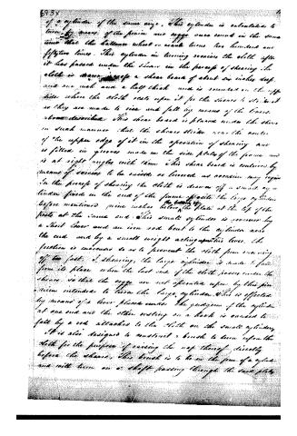
of a cylinder of the same size, this cylinder is calculated to turn by means of the pinion and coggs once round in the same time that the balance wheel or weight turns two hundred and fifty-two times. This cylinder in turning receives the cloth after it has passed under the shears in the process of shearing. The cloth is drawn over a shear board of about six inches deep and one inch and a half thick and is mounted on the opposite side where the cloth rests upon it for the shears to strike it as they are made to rise and fall by means of the levers above described. This shear board is placed under the shears in such manner that the shears strike near the centre of the upper edge of it in the operation of shearing and is fitted in grooves made in the side plates of the frame and is at right angles with them. This shear board is contained by means of screws to be raised or lowered as occasion may require.
In the process of shearing the cloth is drawn off a small cylinder fixed in the end of the frame opposite the large cylinder before mentioned. This small cylinder is governed by a short lever and an iron rod bent to the cylinder near the end and by a small weight acting upon this lever. The friction is increased so as to prevent the cloth from running off too fast. In shearing, the large cylinder is made to fall from its place when the last end of the cloth passes under the shears so that the coggs are not operated upon by this pinion intended to turn the large cylinder. This is effected by means of a lever placed under the periphery of the cylinder at one end and the other resting on a hook is caused to fall by a rod attached to the cloth on the small cylinder.
It is also designed to construct a brush to turn upon the cloth for the purpose of raising the nap thereof directly before the shears. This brush is to be in the form of a cylinder and will turn on a shaft passing through the same plate.
Page 7.
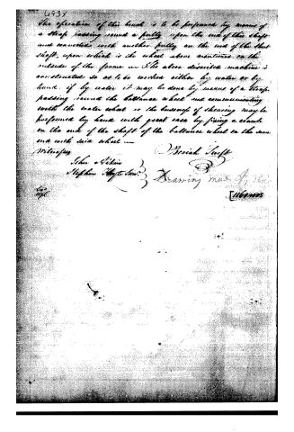
The operation of this book is to be performed by means of a strap passing round a pully upon the end of the shaft and connected with another pully on the end of the shaft, upon which is the wheel above mentioned on the outside of the frame. The above described machine is constructed so as to be worked either by water or by hand; if by water it may be done by means of a strap passing round the balance wheel and communicating with the water wheel or the business of shearing may be performed by hand with great ease by fixing a crank on the end of the shaft of the balance wheel on the same end with said wheel.
Witnesses:
John O'Brien
Stephen O'Byrne
Breviah Swift
Drawing made by him
[11601775]
About this record
- Patentee
- DATAMP
- Date
- DATAMP, USPTO records, Burke's List of Patents (1847)
- Invention
- DATAMP
- Listed in
- the Name and Date index of patents, DATAMP, USPTO records, Jim Shaw's X-patent list, S. A. Elliot's printed list of patents, Burke's List of Patents (1847)
- The sources give different dates; the date shown is the one most of them agree on.
- S. A. Elliot's printed list of patents gives the same name and date.
- Burke's 1847 Patent Office list gives the same patent.