

Drawings and documents
National Archives restored drawings: drawing
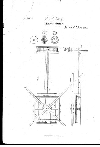
James H. Cory's Patent Drawing for a Machine for Utilizing Horse Power

National Archives, Restored Patent Drawings (Record Group 241) · Full-size scan at the National Archives · Catalog record
Show the text on the drawing Hide (104 words)
Words on the drawing as machine-read by the National Archives; not checked. Useful mainly for searching.
MECHANICAL POSTE / 185 Mechanical Motors; / powerls Gears. / CLASSI.ICATION / 6943.4 / DIVISION. / Sames H. Cory. / FL / Horse Power. / Patented / .4 / Fig 1. / References. / Frame, / Horse wheel shatt / Horse wheel / Flunge / E. / Lovers / C' / Pinion / Ct wrought iron shaft / Teab Fiy / H Second motion nheel / Curved timber / Cap piece / K Ratchet wheel / I/M G rouved wheel inside K1 / Universal joint / Catches / C outside plate / Eig 2 / Patent Hice 26th June in / Scale to Figure 14.2. / Made under under the di of the Consumpro / Patents in conformity with act March 1837. / Herrizi Winorth / Comin promer of itents
USPTO scan
The patent as scanned by the USPTO
-
 Page 1
-
 Page 2
-
 Page 3
-
 Page 4


U.S. Patent and Trademark Office · Google Patents
Show the transcription Hide (1,256 words)
Machine transcription (LightOnOCR) of the pages as scanned by the USPTO, most of them the handwritten copies made when the records were restored after the 1836 fire. Not checked; it can misread handwriting, so compare it with the scan.
Page 1.
6943X
J. H. Cory,
Horse Power.
Patented Feb. 27, 1832.

A.M. PHOTO-LITHO. CO. N.Y. (OSBERNE'S PROCESS)
Page 2.
Feb 27, 1892
James H. Gray, Betel Township, Ohio
Settlers Patent
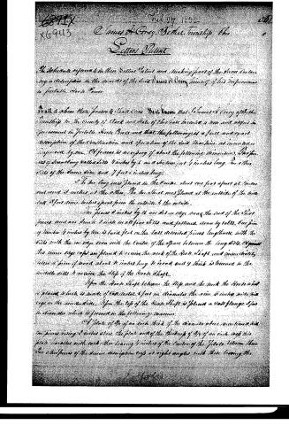
The Inventors referred to in their Settlers Patent and making part of the above containing a description in the names of the said James H. Gray himself of his improvements in Portable Horse Power.
To all to whom these presents shall come, We know that James H. Gray of Betel Township in the County of Clark and State of Ohio have invented a new and useful improvement in Portable Horse Power and that the following is a full and exact description of the construction and operation of the said Machine as invented and improved by me. Of frame is necessary of about the following dimensions. The pieces of standing called Sills 4 inches by 6 and a distance 4 feet 4 inches long. The other Sills of the same size and 7 feet 6 inches long.
The two long and placed in the Center about one foot apart at bottom and about 3 inches at the other. The two short ones placed at the outside of the Sills but 3 feet nine inches space from the outside to the outside.
The pieces 8 inches by 6 are set on edge near the end of the short pieces and are stuck 2 inches in all four Sills and fastened down by bolts. One piece of timber 4 inches by ten is laid flat on the last described pieces lengthwise with the Sills with the one edge even with the Center of the Space between the long Sills. Against this inner edge rests are placed to receive the neck of the Horse Shaft and immediately below a piece of wood about 16 inches long 8 broad and 9 thick is tenoned in the outside Sills to receive the Step of the Horse Shaft.
Upon the Horse Shaft between the Step and the neck the Horse wheel is placed which is made of Cast Metal 4 feet in diameter the rim 8 inches wide with keys on the inner side. Upon the top of the Horse Shaft is placed a Cast Flange 3 feet in diameter which is formed in the following manner.
A plate of 3/4 of an inch thick of the diameter above mentioned with two pieces rising 2 inches above the plate and of the thickness of 3/4 of an inch and this plate parallel with each other leaving 1 inches of the Center of the plate between them. The other pieces of the above description set at right angles with these leaving the
Page 3.
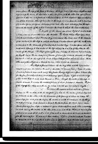
same space. The edge of the plate of the draw thimble rises to the same height on each segment of the circle. So that when a similar plate with the other side up is placed opposite to this one and fastened with four bolts one in each segment opposite to from one side a circular sheet of 4 inches in thickness 2 feet in diameter with 4 mortices of 4 inches square at equal distances from each other and extending from the edge towards the centre of the wheel to receive the lances to which the lances are attached.
The length of the lances are about 11 feet 6 inches with a space from one to another near the middle. The Horse tail shaft before mentioned will be about 2 feet 8 inches long connected at the lower end to the diameter of the wheel to fit the step in which it stands 4 inches square up to the neck which is rounded to the diameter of 4 inches and 4 inches long 4 inches square above the neck and tapering to 3 1/4 inches at the top which fits to a hole of the diameter the centre of the flange. A shaft of wrought iron 6 inches in diameter 10 feet 6 inches in length has on the one end a projection of about 9 1/2 inches in diameter with cogs similar to work in the cogs of the Horse wheel both of which wheels are fixed. On the other end of this shaft is a second section wheel 4 feet in diameter.
This shaft is placed between the two long arms and the 4 feet wheel rests in a frame fastened to the end of the shaft. A current piece of 1 inch 10 inches broad is fastened near each end of this frame leaving sufficient space between them for the four feet wheel to turn and extending up to a proper height to receive a cap of 2 1/4 inches thick to rest and turn on them through the centre of this cap a motion is made to receive the ratchet pinion of about 9 inches in diameter. The face of the cogs of this wheel and the one to which it works are 2 1/2 inches in length.
This wheel (the ratchet wheel) exhibits a plane surface on the one side with the exception of a hole in the centre of about 1 1/2 inch in diameter, on the other side the diameter of the opening is about 1 1/2 inches. At about half an inch from the surface the metal is made to commence at nothing and project 1/4 an inch inward towards the centre from the circle before mentioned forming four steps or catches at equal intervals from each other and extending in such leaving the metal on the other side 1/4 an inch thick. A small circular piece of about 1/4 an inch thick with a hole of 1 1/2 inch in diameter in the centre is made to fit the vacancy from the outside these catches. A piece of metal 2 inches 1 inch in diameter and 1/4 inch thick with a hole in the centre 1 1/2 inch diameter and a groove
Page 4.
round the center of the circumference about 4 1/2 inches in width and 1/2 in depth.
4 holes are drilled through the edges of the groove at equal intervals. One Catch of wrought iron 1/4 an inch square and 1/2 inches long with a hole drilled through the one end through which runs the holes in the edges of the groove across and fast, under each of these catches is placed a brass steel spring which tends to throw the one end out about 1/4 an inch beyond the edge of the groove.
This is then placed in the center of the wheel last above mentioned in such fashion that the ends of the last mentioned catches bear against the ends of the first mentioned catches. The wheel thus constructed is placed in the center of the inner and front of the shaft of about 1 1/2 inches long and 1 1/2 in diameter and is prevented from turning on that shaft by a dovetail groove made on the side of the shaft and on the inner part of the inner wheel which is fitted by a key.
The advantage of a wheel of this construction is that if the Horse were to stop while the machine is in a full motion, the inner part of the wheel would run around the machinery until its force is spent thereby guarding the works from the injury which might be sustained by a sudden check.
By means of a universal joint attached to the last mentioned shaft, this machinery may be conveniently applied to threshing machines, Cutting Machines, Grindery, Breeches, Turning Lathe &c. The foregoing improvements may be varied in size and proportions to suit the talents for which it is intended to be applied.
Patented
Saml. Wats
Henry H. Stantakes
James H. Corry.
Patented 27 February 1832
About this record
- Patentee
- DATAMP
- Date
- the Name and Date index of patents, DATAMP, USPTO records
- Invention
- DATAMP
- Listed in
- the Name and Date index of patents, DATAMP, USPTO records, Jim Shaw's X-patent list, Burke's List of Patents (1847)
- Burke's 1847 Patent Office list gives the same patent.