

Drawings and documents
National Archives restored drawings: drawing
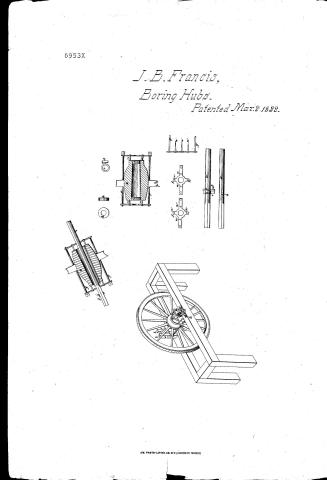
John B. Francis' Patent Drawing for a Machine for Boring Hubs

National Archives, Restored Patent Drawings (Record Group 241) · Full-size scan at the National Archives · Catalog record
Show the text on the drawing Hide (139 words)
Words on the drawing as machine-read by the National Archives; not checked. Useful mainly for searching.
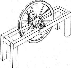
144. WOOD WORKING. / C. / 10 / 3. SPECIAL WORK MACHINERY. / [31] Boring Hubs. / #250 / John B. Francis / Vol. 393 / CLASSIFICATION / Patented March 2. 1832. / 6953 / Boring Hubs. / DIV ISION. / K2 / Gange is wedge K. / OI / wheels. / Section of Hub and plates / with the wheels h h inserted. / WW / Inviewof view of plates. / n. / n. / Plates / 12 / References a. iron spindle b mortide. c the bit d the gange. cethe seiews. f f. iron plates with wings. / gg. non годи with serews. h. coooden wheel. i the band gauge K.thewedge. L. l.uprights of the frame. / m.cap. n.n.nn. iron points .ohub. S. the entire wheel. / Patent office December 16,1841. / made under the direction of the Commissioner / of Patents in conformity with act of 3' march 1837. / Hd Sumooth / ch. L. Aleischman fact. / Commissioner of Patents
USPTO scan
The patent as scanned by the USPTO
-
 Page 1
-
 Page 2
-
 Page 3
-
 Page 4


U.S. Patent and Trademark Office · Google Patents
Show the transcription Hide (1,040 words)
Machine transcription (LightOnOCR) of the pages as scanned by the USPTO, most of them the handwritten copies made when the records were restored after the 1836 fire. Not checked; it can misread handwriting, so compare it with the scan.
Page 1.
6953X
J. B. Francis,
Boring Hubs.
Patented Mar. 2, 1832.
AM. PHOTO-LITHO. CO. N.Y. (OSBORNE'S PROCESS)
Page 2.
6953X
Mar 2, 1892
John B. Francis, Loudon County Virginia,
Letters Patent.
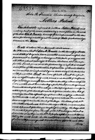
The Schedule referred to in these Letters Patent and making part of the same, containing a description in the words of the said John B. Francis, himself of his improvement in the machine for boring or cutting out the ends of the ends of wheel carriages to receive the Boxes.
To all to whom these presents shall come, —
Be it known that I John B. Francis in the county of Loudon and state of Virginia, have invented a new and useful improvement in cutting or boring out the ends of wagons and all other wheel carriages to receive the boxes, also the cups for the Sinech-pins, and the following is a full and exact description of the construction & operation of the said machine as invented or improved by me according to the model herewith presented. First, an iron spindle about two feet six or eight inches long made round and smooth of uniform size, and large enough to prevent it from trembling, with one end square and a mortise about two inches long a foot at least from the square end to receive the shanks of the bits and chages, with a tapering screw or wedge inserted opposite of the shanks aforesaid, to tighten or slacken them, bits of several sizes to suit the different sizes of boxes will be necessary, with shanks to fit the mortise in the spindle, leaving room between it and the screw or wedge to receive the shank of the chage. The blade of the bit should stand backward to show the edge with the inner corner forward to prevent splitting or roughing in cutting. The chage should be made to pass before the edge of the bit bearing on the cut in the sides so as to give the bit its proper depth or prevent it from taking too much work. In the next place must be made two plates of iron with four wings each ten inches long opposite each other.
Page 3.
those of one plate to suit the large end, and those of the other the smaller end of the Hub, also two longer wings to each plate opposite each other, about one and a half inches longer from the center of the plate than the semi diameter of the largest Hub, with a point of iron three inches in length, with the same on each wing at equal distances from the center, also half inch holes made near the extremities of the long wings with an eyelet in two of them, two iron rods must be made to fit the said holes with long screws out on one end of them the other end with a head and hole through it to receive a mandrel to turn them; the rods should be about twenty-one inches by, the plates must have holes in their centers to admit the spindle, the tighter the better, so that it can be inserted or drawn out with ease. There is another large necessary which is a band of iron made to fit the spindle with substance sufficient to admit a wedge or key to tighten and hold it stationary; it will also be necessary for all persons using said machine, to provide wooden wheels (which I shall denominate center wheels) made to fit the spindle, and the inside of different sized boxes. The manner of using said machine is as follows; the box must be gouged out in the usual way to the inside of the box, then the center wheels introduced into each end and the spindle passed through them, the plates to be slipped on the spindle at their respective ends, the long screws to be inserted into their places in the wings with the rods passing between the spokes of the wheel; the points are then entered into the ends of the Hub and the screws wrapped up to hold them to their places; the spindle is then drawn out and the center wheels taken out, the spindle is then returned and the first mentioned large placed in the mortice and made tight with the tapered screw or wedge, the spindle is run through the box until stopped by the bit, the other gouge is then slipped on the opposite end so far that the box
Page 4.
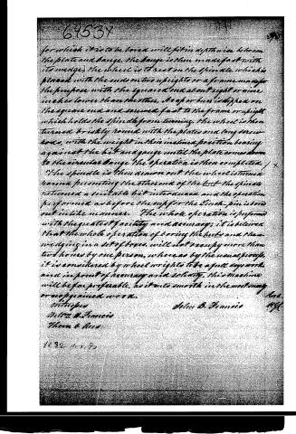
for which it is to be bored will fit in depthwise between the plate and gauge, the gauge is then made fast with its wedge, the sheet is to rest on the spindle, which is placed with the end on two uprights or a frame made for the purpose with the square end about eight or nine inches lower than the other, a leaf or bar is dipped on the square end and screwed fast to the frame or upright, which holds the spindle from turning. The wheel is then turned briskly round with the plates and long screw-beds, with the weight in their inclined position bearing against the bit and gauge until the plate comes down to the circular gauge. The operation is then completed.
The spindle is then drawn out, the wheel is turned round presenting the other end of the bit, the spindle retained a suitable bit introduced and the operation performed as before. The cup for the linch-pin is bored out in like manner. The whole operation is performed with the greatest facility and accuracy; it is believed that the whole operation of boring the locks and then wedging in a set of keys will not occupy more than two hours by one person, whereas by the usual process, it is considered by wheelwrights to be a full day's work, and in point of accuracy and solidity, this machine will be far preferable, as it cuts smooth in the most easy or ungrained work.
Witnesses
John B. Francis
William B. Francis
Thom & Ross
1032 10/1/50
Published accounts: journal notice
Notice in the monthly list of patents, with remarks
Journal of the Franklin Institute, new ser., vol. 10 (1832), p. 156 · View the page
3. For Boring or cutting out the ends of the Hubs of wheel carriages to receive the Boxes; John B. Francis, Louden county, Virginia, March 2.
Remarks. The hub to be bored is fixed within a sort of cage work composed of different pieces of iron adapted to the purpose of holding it centrically, and steadily, on a wooden frame. It is sustained upon this frame by making it the bearings for a cylindrical iron spindle which passes through the hub, and upon which it is capable of being turned round. For this purpose the spindle slides through holes in iron plates forming a part of what we have called the cage work, and into these holes the spindle fits accurately. By means of a mortise in the spindle, suitable cutters are fixed by wedging, or otherwise, which cutters are adapted in size and structure to the hole to be cut. When the respective parts are fixed in their proper places, the spindle is secured from turning round; the hub, or wheel, is then turned against the cutter, and the hole sunk to the proper depth.
DATAMP: illustration
Illustrations from DATAMP

DATAMP (Directory of American Tool and Machinery Patents), via the Internet Archive · Archived DATAMP page
About this record
- Patentee
- the Journal of the Franklin Institute, Journal
- Date
- the Name and Date index of patents, DATAMP, USPTO records
- Invention
- DATAMP
- Listed in
- the Name and Date index of patents, DATAMP, USPTO records, Jim Shaw's X-patent list, the Journal of the Franklin Institute, Burke's List of Patents (1847)
- The patentee's full name comes from the Franklin Institute's journal.
- Burke's 1847 Patent Office list gives the same patent.