

Drawings and documents
National Archives restored drawings: drawing
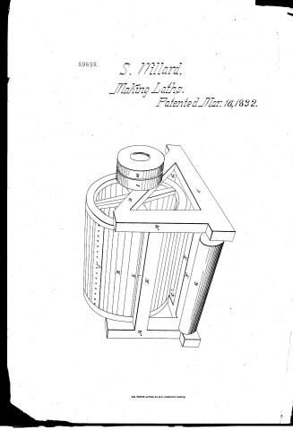
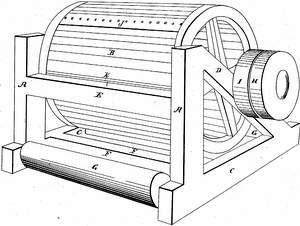
Simon Willard's Patent Drawing for a Revolving Lath-Cutter

National Archives, Restored Patent Drawings (Record Group 241) · Full-size scan at the National Archives · Catalog record
Show the text on the drawing Hide (86 words)
Words on the drawing as machine-read by the National Archives; not checked. Useful mainly for searching.
144. WOOD WORKING MACHINES. / Lumber Sath Machines / Slicers, Rotary & Oscillating. / $1- / CLASSIFICATION / SIMON WILLARD / 6969-4 / DIVISION. / Revolving Lath-Cutter. / A.A Uprigt Posts / Patented 16th Marcb.1832. / B. Hollow Cyltnder / C. Sills of the supporting frame / D. Tnotined-beam / E. Horezontal pert sumporting Tronbar / F. Tumbers framed into sills - / G. Rollers rouna which the carerass moves / H Loosepulley / I. Driveng palley / K. Ironbar fasteneato Girt E / J. Revolving Cutter / a Stricklana DAL
USPTO scan
The patent as scanned by the USPTO
-
 Page 1
-
 Page 2
-
 Page 3
-
 Page 4
-
 Page 5
-
 Page 6
-
 Page 7
-
 Page 8
-
 Page 9


U.S. Patent and Trademark Office · Google Patents
Show the transcription Hide (2,654 words)
Machine transcription (LightOnOCR) of the pages as scanned by the USPTO, most of them the handwritten copies made when the records were restored after the 1836 fire. Not checked; it can misread handwriting, so compare it with the scan.
Page 1.
6969X
S. Willard,
Making Laths.
Patented Mar. 16, 1832.
AM. PHOTO-LITHO. CO. N.Y. (OSBORNE'S PROCESS)
Page 2.
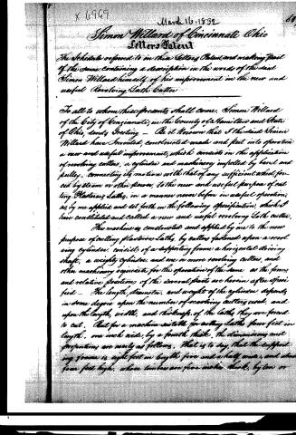
X 6969
March 16, 1832
Simon Willard of Cincinnati Ohio
Letters Patent
The Schedule referred to in this Letters Patent, and making part
of the same, containing a description in the words of the said
Simon Willard himself of his improvement in the new and
useful Revolving Sash Cutter
To all to whom these presents shall come, Simon Willard
of the City of Cincinnati, in the County of Hamilton and State
of Ohio, sends Greeting — Be it known that I the said Simon
Willard have Invented, constructed made and put into operation
a new and useful improvement, which consists in the application
of revolving cutters, a cylinder and machinery impelled by hand and
pulley, connecting its motion with that of any sufficient wheel, pro-
cured by steam or other power, to the new and useful purpose of cut-
ting Plastering Sashes, in a manner never before in useful operation,
as by me applied and set forth in the following Specification, which I
have constituted and called a new and useful revolving Sash cutter.
This machine as constructed and applied by me to the new
purpose of cutting plastering Sashes, by cutters fastened upon a revolv-
ing cylinder, consists of a supporting frame, a horizontal driving
shaft, a weighty cylinder, and one or more revolving cutters, and
other machinery requisite for the operation of the same as the forms
and relative positions of the several parts are herein after speci-
fied — The length, diameter, and weight of the cylinder depends
in some degree upon the number of revolving cutters used, and
upon the length, width, and thickness of the Sashes they are forced
to cut. But for a machine suitable for cutting Sashes four feet in
length, one inch wide, by a fourth thick, the dimensions and
proportions are nearly as follows. That is to say, that the support-
ing frame is eight feet in length, five and a half wide, and about
four feet high, whose timbers are five inches thick, by ten or
Page 3.
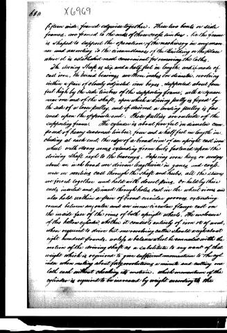
fifteen wide, framed edges together. These two bouts or side frames, are framed to the ends of three or four timbers. On the frame is shaped to support the operation of the machinery in any manner and according to the circumstances of the building or the place where it is established most convenient for removing the laths.
The driving shaft is six and a half feet in length, and if made of cast iron, the turned bearings are three inches in diameter, revolving within a pair of closely adjusted iron boxes, supported about four feet high by the side timbers of the supporting frame, with a square near one end of the shaft, upon which a driving pulley is fixed by the side of a loose pulley, and if desired a tensioning pulley is fastened upon the opposite end. These pulleys are outside of the supporting frame. The cylinder is about five feet in diameter composed of heavy seasoned timbers, four and a half feet in length including at each end, the edge of a broad rim of an upright cast iron wheel with strong arms extending from hubs fastened upon the driving shaft next to the bearings. Depending iron keys or wedges about an inch broad are driven lengthwise in grooves, and crosswise in mortises cast through the shaft and hubs. All the sleeves are forced together and held with dowel pins, or held by their ends inserted and pinned through holes cast in the wheel rims, and also held within a pair of broad circular grooves, extending round between an outer and an inner circular flange cast on the inside face of the rims of both upright wheels. The enclosure of this hollow cylinder, whether it consists entirely of iron or of wood, when required to drive but one revolving cutter should weigh about eight hundred pounds, unless a balance wheel be connected with the motion of the driving shaft as a substitute to any want of that weight which is required to give sufficient momentum to the cylinder when making about forty revolutions a minute and cutting one lath each without checking its motion, which momentum of the cylinder is required to be increased by weight according to the
Page 4.
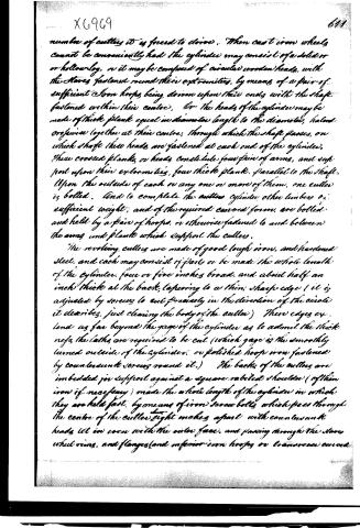
number of cutters it is forced to drive. When cast iron wheels cannot be conveniently had the cylinder may consist of a solid or or hollow log, or it may be composed of circular wooden heads, with the staves fastened round their extremities, by means of a pair of sufficient iron hoops being driven upon their ends with the shaft fastened within their centre. Or the heads of the cylinder may be made of thick plank equal in diameter length to the diameter, halved or joined together at their centre, through which the shaft passes, on which shaft these heads are fastened at each end of the cylinder. These crossed planks, or heads constitute four pairs of arms, and support upon their extremities, four thick planks, parallel to the shaft. Upon the outside of each or any one or more of them, one cutter is bolted. And to complete the cutter cylinder other timbers of sufficient weight, and of the required curved forms, are bolted and held by a pair of hoops, or otherwise fastened to and between the arms and planks which support the cutters.
The revolving cutters are made of good tough iron, and hardened steel, and each may consist of parts or be made the whole length of the cylinder, four or five inches broad, and about half an inch thick at the back, tapering to a thin, sharp edge (it is adjusted by screws to cut precisely in the direction of the circle it describes, just clearing the body of the cutter) Their edges extend as far beyond the gage of the cylinder as to admit the thickness the laths are required to be cut (which gage is the smoothly turned outside of the cylinder, or polished hoop iron fastened by countersunk screws round it.) The backs of the cutters are imbedded for support against a square, rabited shoulder (of thin iron if necessary) made the whole length of the cylinder in which they are held fast, by means of iron screw bolts, which pass through the centre of the cutter, tight makes apart with countersunk heads let in even with the outer face, and passing through the stave wheel rims, and flanges (and inferior iron hoops or transverse curved
Page 5.
supporters when requiring their support) by means of nuts being screwed on the interior end of the bolts by which the cutters are firmly held from springing when cutting the laths. Attention to letting on the cutters a sufficient space is made between the fore part of them and the cylinder, for the admission and free discharge of the laths the same way they come on from the boards edge to fall before the slower descent of the revolving cutter (which laths may be forced out by springs if the motion is great). The cutters are fastened on the cylinder a little inclined, consequently so spiral that their revolving edges will coincide with the straight horizontal acute corners of an iron bar imbedded, and fastened along the upper inside corner of a substantial girder of the supporting frame as near to it as can well be without danger of contact.
When the laths are required to be sawed off by the same machine any required number of short curved segments of a suitable circle of a saw are fastened, with the teeth extending outwards, upon the outer surface of the cylinder, just before the cutters at such distances from each as the length of the laths require to be cut. Projecting no further from the face of the cylinder than to just saw sufficiently deep into the edge of the long board as may be required to cut each lath entirely off before they become out lengthwise by the cutters. The fore ends of each of these circular saw segments terminate close at the surface of the cylinder, gradually increasing in width towards their back ends, which reach to within a few inches of the cutting edge to give room for the shortly sawed laths to fall free of any interference of the saw.
For sawing off the laths or other useful pieces, immediately before cutting them lengthwise of any suitable length or breadth for various uses. The cylinder may consist of flat rimmed iron wheels of equal size from two to four feet in diameter, fastened upon the shafts in a manner calculated to be movable along it. They are driven or weighed fast at any required dis
Page 6.
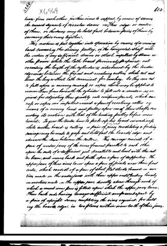
lance from each other for their rims to support, by means of screws the curved segments of circular saws on their edges or centre of them, or the saws may be held fast between pairs of them by screwing their rims together.
This machine is put together into operation by means of a moving band connecting the driving pulley, of the horizontal shaft with the motion of any sufficient drum or wheel, impelled by steam or other power while the lath board previously prepared, not exceeding the length of the cylinder is, introduced by the tender edgewise between the fixed and revolving cutters which cut and throw the long or short lath convenient for bending. So they are cut to fall upon a moving carriage, or ropes, which may be applied to remove them from beneath the cylinder to fall into a measure as required for adjusting their quantity into uniform parcels, which car raps or ropes are impelled round a pair of revolving rollers by means of a moving band and pulley upon one of their shafts connecting its motion with that of the tending pulley before mentioned. To give the tender time to pick up his board in reading, while another board is cutting, a pair of pieces constituting a feeding carriage may be made to grasp and hold fast the board's edge and advance the same between the cutters. This carriage consists of a pair of under jaws of the pieces framed parallel to each other upon the ends of a sufficient girder parallel to and level with the cutter beam, and moves back and forth upon a pair of supports. The upper jaws of these pieces turn upon a pair of joints near their front ends, which consist of a pair of short flat slides framed in mortises made in the under jaws with their upper ends, tending loosely in mortises made in the upper jaws directly above through each of which a round iron pin is fitted upon which the upper jaws turn. Their back ends having leverage sufficient are pressed apart by a pair of aspright screws completing the pieces required for holding the board's edges in two places within iron teeth of their jaws.
Page 7.
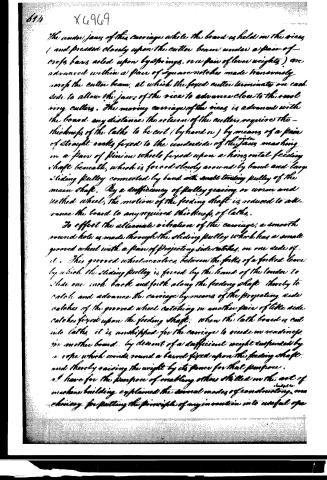
The under jaws of the carriage, while the board is held in the vice, and pressed closely upon the cutter beam under a pair of cross bars acted upon by springs, or a pair of lever weights, are advanced within a pair of square notches made transversely across the cutter beam, at which the fixed cutter terminates on each side to allow the jaws of the vice to advance close to the revolving cutters. The moving carriage of the vice is advanced with the board any distance the return of the cutters requires the thickness of the laths to be cut (by hand or) by means of a pair of straight notches fixed to the underside of the jaws, meshing in a pair of pinion wheels fixed upon a horizontal feeding shaft beneath, which is forced slowly around by band and large sliding pulley connected by band with small turning pulley of the main shaft. By a sufficiency of pulley gearing or worm and tethed wheel, the motion of the feeding shaft is reduced to advance the board to any required thickness of laths.
To effect the alternate vibration of the carriage, a smooth round hole is made through the sliding pulley which has a small grooved wheel with a pair of projecting side notches, on one side of it. This grooved wheel revolves between the forks of a forked lever by which the sliding pulley is forced by the hand of the tender to slide one inch back and forth along the feeding shaft thereby to catch and advance the carriage by means of the projecting side notches of the grooved wheel catching in another pair of little side notches fixed upon the feeding shaft. When the lath board is cut into laths, it is unshipped for the carriage to reside in readings in another board, by descent of a sufficient weight suspended by a rope which winds round a barrel fixed upon the feeding shaft, and thereby raising the weight by its power for that purpose.
I have for the purpose of enabling others skilled in the art of machine building explained the several modes of constructing, one choosing for putting the principle of my invention into useful operation.
Page 8.
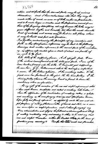
ration, and set forth that the several parts may be of various dimensions. And I have calculated also that they may be made either of wood, or iron or of both, as far as practicable, and to be made larger or smaller, and the proportions varied from those of the foregoing descriptions, not only because the laths may require different lengths and breadths, but that the most durable kind of materials and means may be had in all places where it may be built and put into operation.
For further understanding the principle of my invention set forth in this specification references may be had to the following drawings, and written references, to the several parts of the machinery, as appears represented upon a scale of about one fourth of an inch to the foot.
C.C. Sills of the supporting frame. A.A. upright posts. D one of the inclined beams framed into the sills and posts. F one of the lower timbers framed into the sills. O horizontal girder supporting the iron bar. G.G. Rollers round which the canvas is impelled to move. B. the hollow cylinder. C the revolving cutter. K the fixed iron bar fastened to the girder. Hb. the loose pulley. I the driving pulley whereon the moving board is forced to drive the machinery when in operation.
As my right of the invention of this new and useful improvement, what I have made known, constitute and called a revolving Lath Cutter, I claim the application of the combination of revolving cutters, a cylinder and machinery as the accompanying drawings and specification herein before fully and plainly represent, as applied by me to the new and useful purpose of cutting plaster or Laths of boards and slabs, in a manner never before in useful operation, and I claim for myself my heirs administrators and assigns the full and exclusive right and liberty of making, constructing, using and vending to others to be used my said new and useful invention, within the United States for the term of fourteen years, according to Law for that term made and provided.
Page 9.
In testimony that the foregoing is a true specification and designation of my claim of said new and useful invention, I have hereunto subscribed my name the twenty eighth day of January eighteen hundred and thirty two.
Attest:
Nathaniel Hootley
Joseph M. Houston
Simon Willard
Patented 16th March 1832
Published accounts: journal notice
Notice in the monthly list of patents, with remarks
Journal of the Franklin Institute, new ser., vol. 10 (1832), p. 162 · View the page
The silk reel is a very simple instrument, and although it has been made in various forms, its essential parts are the same. The present patentee has described his own form of reel, but without telling what particular advantages it possesses over others, or claiming any part as As we are unable to supply these deficiencies, we shall not attempt to follow him in his description. new. 19. For a Revolving Lath Cutter; Simon Willard, Cincinnati, Hamilton county, Ohio, March 16.
Remarks. A cylinder, which, for laths of the ordinary length, may be about five feet in diameter, and of the length of the lath, is made to revolve on a strong iron shaft. The ends of the cylinder are best made of cast iron, as the whole machine must have great strength and weight. The periphery of the cylinder is of wood, and turned perfectly true; one or more cutters, formed of strong flat iron bars, faced with steel, extend from end to end of the cylinder, the distance from which to the cutting edge forms the gauge for the thickness of the lath. A horizontal bar of wood, having on it one of iron, serves as a rest upon which the timber to be cut is held. The edge of the board, held upon the rest, is forced up against the face of the cylinder, whilst the latter is revolving. The width of the lath is determined by the thickness of the board used. There are several accessory parts, such as a revolving apron, or other contrivances, for carrying off, and collecting together, the laths, but these we do not think it necessary to describe. The claim is to the combination of revolving cutters, a cylinder, and other machinery, as described, for the purpose of cutting laths.
DATAMP: illustration
Illustrations from DATAMP

DATAMP (Directory of American Tool and Machinery Patents), via the Internet Archive · Archived DATAMP page
About this record
- Patentee
- DATAMP
- Date
- the Name and Date index of patents, DATAMP, USPTO records
- Invention
- DATAMP
- Listed in
- the Name and Date index of patents, DATAMP, USPTO records, Jim Shaw's X-patent list, the Journal of the Franklin Institute, Burke's List of Patents (1847)
- Burke's 1847 Patent Office list gives the same patent.