

Drawings and documents
National Archives restored drawings: drawing
Harrison Holland's Patent Drawing for a Box Machine

National Archives, Restored Patent Drawings (Record Group 241) · Full-size scan at the National Archives · Catalog record
Show the text on the drawing Hide (144 words)
Words on the drawing as machine-read by the National Archives; not checked. Useful mainly for searching.
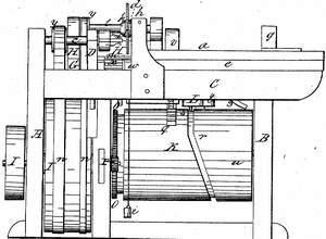
144. WOOD WORKING. / 3. SPECIAL WORK MACHINERY. / [30] Making Boxes. / #250 / #6997x / ASSIFICATION / HARRISON HOLLAND'S / 197 X / Patented 13th April 1832. / DI VISION. / BOX MACHINE / a Front of the machine b, Back of do. C, Mandril of the anger d, Auger e, timber carriage. fi Head block. / 5 Foot block his Vice. 2; weight. k, saw. 2, saw shaft. m, brop tie t row of coys n of 10cogs. - dream 9, Row / of cogs on drum K. r, Groove mar the centre of do. S, boy working in groove. t, Lever. u, bog near lower End of / drum. V, Simi-cog what. w, Anle of do.x, small cog which on do.y, small pulleys. 2, Pin in the and of lap. / 1, Ann of iron 2, Sever to return the carriage. 3, The reach. / Sich elevation. / C' / Top view / /3 / I.
USPTO scan
The patent as scanned by the USPTO
-
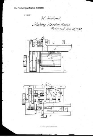 Page 1
-
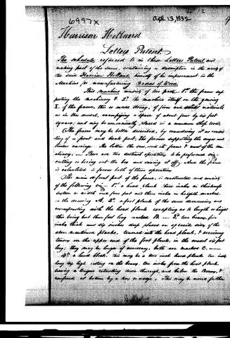 Page 2
-
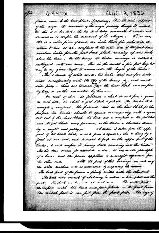 Page 3
-
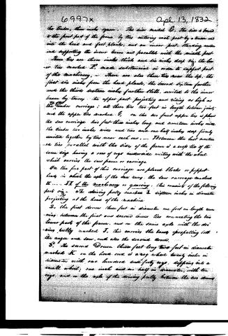 Page 4
-
 Page 5
-
 Page 6
-
 Page 7


U.S. Patent and Trademark Office · Google Patents
Show the transcription Hide (2,365 words)
Machine transcription (LightOnOCR) of the pages as scanned by the USPTO, most of them the handwritten copies made when the records were restored after the 1836 fire. Not checked; it can misread handwriting, so compare it with the scan.
Page 1.
No Printed Specification Available
6997X
H. Holland,
Making Wooden Boxes.
Patented Apr. 13, 1832.

AM. PHOTO-LITHO. CO. N.Y. (OSBORNE'S PROCESS)
Page 2.
6997X
Harrison Holland
Letters Patent.
The schedule referred to in these Letters Patent and making part of the same, containing a description in the words of the said Harrison Holland himself of his improvement in the Machine for manufacturing Boxes of Wood.
This machine consists of two parts,—1st the frame supporting the machinery & 2d the machine itself on the gearing I. of the frame, this is made strong, of firm and solid materials, as in the model, occupying a space of about four by six feet square; and may be conveniently placed in a common shop room.
The frame may be better described, by considering it as consisting of a front and back part, the former supporting the upper and timber carriage—the latter the saw, and its frame & most of the machinery.—There are two distinct operations to be performed viz—cutting or boring out the box and sawing it off, and the frame is calculated to favour both of these operations.
The main or front part of the frame, is constructed and consists of the following viz—1st a head plank three inches in thickness sixteen in width and four feet and three inches in height marked in the drawing A. 2d a foot plank of the same dimensions and corresponding with the head plank, excepting as to length or height this being but three feet long marked B. 3d two beams, five inches thick and six inches deep placed on opposite sides of the above mentioned planks, tenoned into the head plank, & receiving tenons on the upper end of the foot plank; in the model is flat long; they may be longer if necessary, both are marked C.
4th a head block, this may be a two inch hard plank, ten inches long six high resting on the beam, ten inches from the head plank, having a tongue extending down through, and below the beams, & confined at bottom by a key or wedge, this may be moved further
Page 3.
from or nearer to the head plank, if necessary. It is the main support of the auger. The mandrel of the auger passing through it marked D, this is in two parts; the top part being removable to receive and screwed on to confine the mandrel of the auger. 5th, an ear, this is a solid piece of wood, two inches thick five inches wide at bottom & two at top, confined to the outer side of the front beam near the timber inch from the front head plank, running up nine inches above the beam. On the beam the timber carriage so called to distinguish sets and many. This in the model is five feet long but may be any given length to accommodate the length of the timber.
This is made of solid wood, two inches deep and five inches wide corresponding with the tops of the beam, viz., such are the side pieces—these are tenoned into the head block and confined by ties, or rather connected by ties.
On each of these is fastened a cleat so as to form a groove on each side, in which a foot block is placed. The timber to be wrought is confined; the forward end in the head block for this purpose the timber should be square corresponding with a square cut out of the head block, the hind end is confined in the foot block and the foot blocks move forward, as the timber is shortened drawn by a weight and pulley.
A certain is taken from the upper part of the head block, so as to form a square, this is hung by a joint at one end, and is made to prop on the upper part of the timber, so as to confine it having teeth running into the timber. This has been called for distinction a vice, it acts on the principle of a lever, and the power applied is a weight suspended from the other end.
All the parts of this carriage as well as of the whole machine will be understood by inspecting the model. The back part of the frame is firmly united with the other part. The back side consists of what may be called a side plate and thin part. The feet are tenoned at each end. The outer parts correspond with the head and foot planks in the front frame. The middle foot is one foot from the front foot. The edge of
Page 4.
6997x
Apr 13, 1832
the timber, three inches space. This side marked C. This side is bound to the front part of the frame by ties entering each post by a beam and into the head and foot blocks, and an inner post, standing under and supporting the inner beam and parallel with the middle post. These ties are three inches thick and six inches deep, viz, the lower ties marked F, made substantial in order to support part of the machinery. There are also three ties near the top, the first six inches from the head plank, the second sixteen inches under the third sixteen inches further still, united to the inner beam by tenons; the upper part projecting and rising as high as the timber carriage; all these ties two feet in length between joints and the upper ties marked G, on the two front upper ties is placed the saw carriage two feet three inches long and seventeen inches wide the timbers two inches wide and two and one half inches deep firmly united together by ties near each end. Between the last mentioned ties parallel with the sides of the frame is a cross tie of the same size having a row of cogs underneath uniting with the wheel which carries the saw frame or carriage.
On the fore part of this carriage are placed blocks or puppet heads in which the axle of the saw runs, the saw carriage marked H. II of the machinery or gearing, this consists of the following parts viz:
1. The driving pulley marked I, sixteen inches in diameter projecting at the head of the machine.
2. The first drum three feet in diameter one foot in length running between the first and second lower ties connecting the two lower parts of the frame, and on the same axle with the driving pulley marked I, this carries the bands propelling both the upper and saw, and also the second drum.
3. The second Drum three feet long two feet in diameter marked K on the head end is a cog wheel twenty inches in diameter with one hundred and forty cogs, dipping into a small wheel, one inch and one half in diameter, with ten cogs, and on the axle of the driving pulley between the two drums.
Page 5.
this small wheel communicating motion to the second drum.
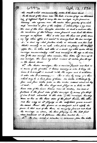
On the barrel of this drum near the head, is a row of cogs one third inch wide of sufficient length to carry the saw carriage as far forward as necessary. Also a groove near the centre three quarters of an inch deep described in form of the ecliptic, in which plays a cog near the end of the lever hereafter described in such a manner that the revolution of the Drum moves forward and back the timber carriage as defined. There is also near the lower end of this drum one cog whose office is to assist in drawing back the saw carriage.
It is a semi cog wheel fourteen inches in diameter and two inches thick, running on an axle whose pivots are fixed in the two front upper ties, or whose axle also is a small cog wheel under the saw carriage communicating with and running in the cogs on the inside side of the saw carriage above named, these latter cogs move up the saw carriage, the semi cog wheel receives its motion from the cogs on the second drum.
D. The timber carriage, this is carried forward and back as in course of the operation it becomes necessary in order to bring the timber to be wrought in contact with the auger and to withdraw it when also it is necessary. This is done by means of a lever which may be a hard piece of timber two inches in thickness by four and four inches wide in the centre reduced about one half at each. This lever hangs and plays on a bolt, on the lower side of the inner beam, near its centre, one end is fastened to the front side of this carriage by means of a strap of iron & bolt attached to the side of the carriage bending down as low as the lower side of the front beam, the other end has a cog in it playing in the ecliptical groove around the second drum this groove is so designed as to apply the power to that end of the lever, in carrying forward and back the carriage as above, the lever playing on the bolt first above mentioned at its fulcrum this lever marked E,
O. The saw wheel is circular in common form ten inches
Page 6.
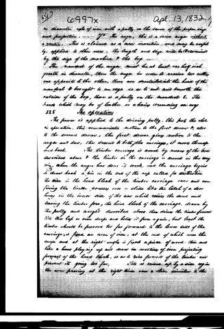
in diameter, axle of iron with a pully on the same of the proper size and proportion. — If the auger, this is a screw auger without a centre. This is claimed as a new invention and may be usefully applied to other uses. The length and size will be determined by the size of the machine & the log.
The mandrel of the auger must be at least one half inch greater in diameter, than the auger in order to receive two cutters, one opposite to the other, these are dovetailed into the head of the mandrel & brought to an edge so as to cut and smooth the outside of the log, there is a pully on the mandrel &. The bands which may be of leather or chains running on any
III The operation
The power is applied to the driving pully, this puts the whole in operation, this communicates motion to the first drum & also to the second drum, the first drum gives motion to the auger and saw, the second to both the carriages, it moves them up and back. The timber carriage is moved by means of the lines described above & the timber in the carriage is moved in the way by, when the auger has done its work, and the carriage begins to draw back a pin in the end of the log called for destruction the vice in the head block of the timber carriage over and confining the timber presses over a slide like the latch of a door hung in the inner side of the car which raises the same and leaving the timber free, the lower block of the carriage, drawn by the pully and weight described above then draws the timber forward till the log or vice stops and holds it from again, but that the timber should be pressed too far forward to the lower side of the carriage, is fixed an arm of iron, at the end of which near the auger and at the right angle is fixed a piece of wood thin and like a beam playing up and down in motion of iron projecting forward of the head block, so as to rise forward of the timber and prevent its going too far. This is raised up by a vice again the arm passing at the right time over a slide similar to the
Page 7.
above fastened to a block projecting in the inner side of the inner frame. The elliptical circle or groove in the second drum in which the cog plays, on the end of the lever means as the power to move the timber carriage forward and back as required; the saw carriage is moved forward by the small wheel on the axle of the semi cog wheel. The second drum communicates motion to the semi cog wheel & this by means of the cogs under the middle piece of the carriage and the small wheel just mentioned the carriage is pushed forward bringing the saw to the timber after it has performed its work and the box raised off. The carriage is pulled back again to make way for the cutting operation by the auger by means of a lever turning on a pivot at its center as a fulcrum resting on the plate one end attached to the timber part of the carriage the other to a reach, & the reach hung on a crank passing through the third upper tier down to the second drum & then turned by means of the cog on the same this is graduated and perforated so as to have this draw the saw and carriage back just in time.
Remarks. 1. The dimensions and proportions above mentioned are assumed as proper and yet they may be varied if necessary, 2. boxes of different sizes may be made by this machine, 3. the lids may be made in the same way, the auger however may be proportionally shorter and the slides moved proportionally nearer the head of the carriage, or 4. boxes may be prepared for the lids by clinching them on to the mandrel of a common turning lathe and grooving the cutting tool or turning slide having the same in end shape as desired. 5. the power may be applied by water or steam or any adequate means. 6. The timber to be worked should be seven square of the size of the box and may be as long as the carriage will admit. Seven times is equally good as that which is answered.
Witness: Samuel J. Dickinson
Harrison Hollans
S. J. Dickinson
222815
Published accounts: journal notice
Notice in the monthly list of patents, with remarks
Journal of the Franklin Institute, new ser., vol. 10 (1832), p. 236 · View the page
18. For machinery for Cutting and Manufacturing Wooden Boxes; Harrison Holland, Belchertown, Hampshire county, Massachusetts, April 13.
Remarks. Wooden boxes are of so many kinds that the above title must fail in furnishing any definite idea of the intention of the machinery, nor does the petition, or the specification, supply the required information; we collect, however, from the drawing and the general description of the apparatus, that the boxes are to be round, and made out of solid stuff. An auger, running in the mandril of a lathe, is used to bore the boxes out, whilst cutters, placed at a proper distance from the auger, form the outside. A sliding carriage in front holds the timber, and this is brought up by proper contrivances against the auger and cutters. A circular saw, upon a sliding carriage, is used to cut the box off. The lids, it is said, may be formed on the same principle, but in this case the auger is to be shortened in due proportion. At the end of the specification we are told that "green timber will answer as well as that which is seasoned. This information is not calculated to throw much light upon the purposes for which the said boxes are to be made, as they will soon lose their rotundity if made of unseasoned stuff. There is no claim made to the machinery as a whole, or in part, excepting that in speaking of the auger with which the boring is to be effected, it is said that it is "a screw auger, without a centre; this is claimed as a new invention, and may be applied to other uses." The fact is, that the screw auger, without a centre, has been applied to other uses long since, and therefore it is not new. We have in our possession one of this description, which was patented so long since that the patent has run out.
DATAMP: illustration
Illustrations from DATAMP

DATAMP (Directory of American Tool and Machinery Patents), via the Internet Archive · Archived DATAMP page
About this record
- Patentee
- DATAMP
- Date
- the Name and Date index of patents, DATAMP, USPTO records
- Invention
- DATAMP
- Listed in
- the Name and Date index of patents, DATAMP, USPTO records, Jim Shaw's X-patent list, the Journal of the Franklin Institute, Burke's List of Patents (1847)
- The residence comes from the Franklin Institute's journal.
- Burke's 1847 Patent Office list gives the same patent.